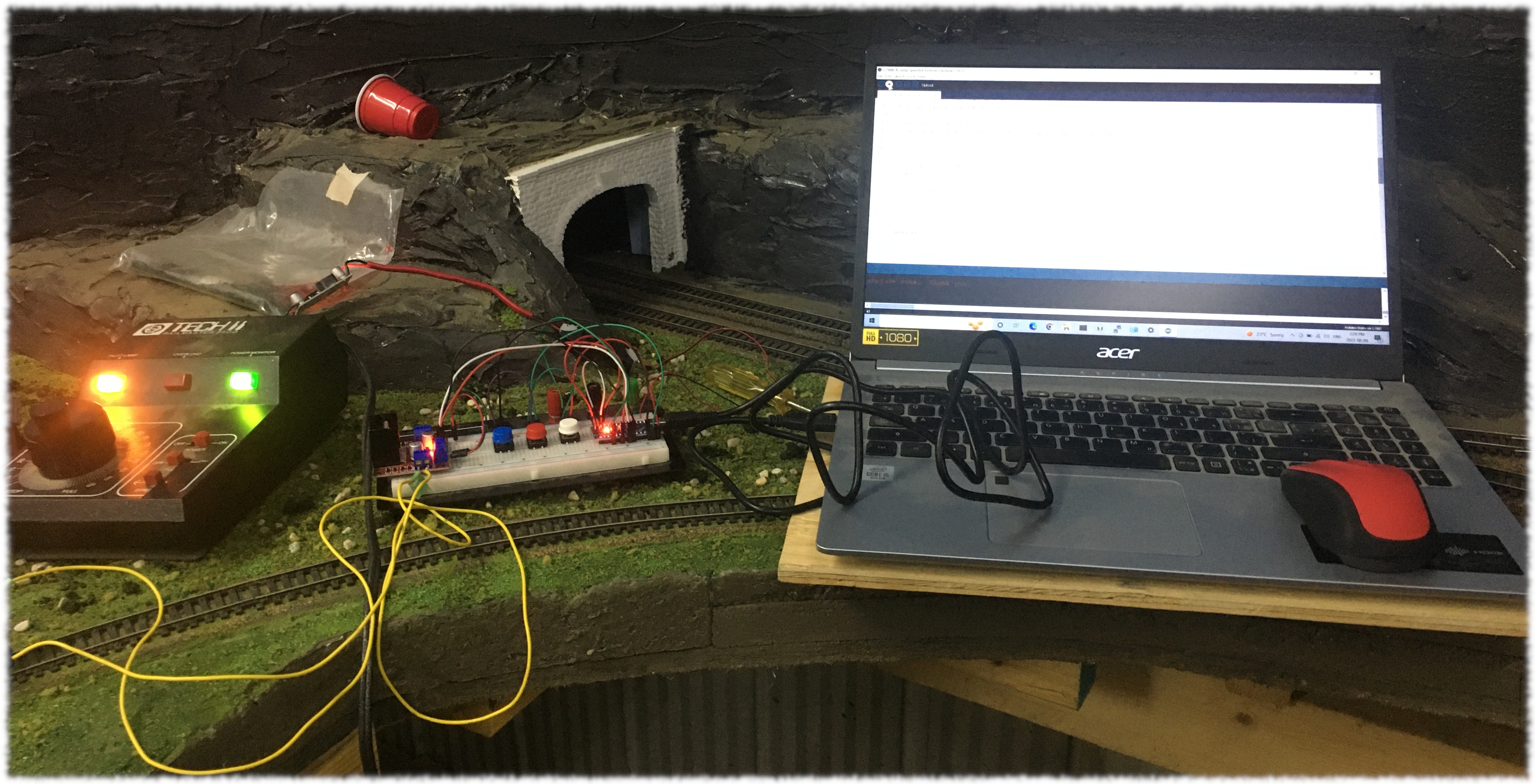
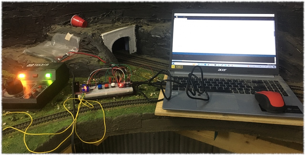
Two videos to demonstrate success.
The first video shows the locomotive powered by the L298N module driven using PWM set to a constant speed.
The second video shows the locomotive increasing and decreasing speed using PWM.


If you are joining this blog post late, here is a summary of my entry for Project 14 Electronics & Design Projects, World in Motion.
My hobby is creating animation in model railroad layouts. My passion is writing. I was successful in controlling the direction and speed of a HO scale model locomotive using PWM. Pulse width modulation (PWM) is a modulation technique that generates variable-width pulses that can be used to control the amplitude of an analog signal. The average value of the analog signal fed to the load can be controlled by adjusting the pulse width of the signal being delivered to a controller. The controller output is on more of the time for longer pulse width and off more of the time for short pulse width.
The project uses an Arduino Nano (knock-off), an L298N power module and the Andrea Lombardo/L298N Arduino Library in Arduino code. The setup uses a DC system power supply feeding the L298N. The Arduino codes deliver PWM pulses to the L289N module to control the speed of the motor. The exercise is part of a bigger project I am involved in to automate a full-scale model layout.
I wrote two sketches to control the motor for this entry. One sketch drives the motor at a constant speed depending on the PWM variable setting. The other sketch ramps up the motor speed and ramps down the motor speed.
The L296 Library supports a range of values from 0-255. A value of 160-180 was the minimum value to get a locomotive to move. A number of different manufactured locomotives were tested. The initial test revealed a motor whine problem using the default PWM signals. The default frequency for PWM is 490Hz or 980Hz depending on the Arduino pin used. Trying to resolve the problem I ran into an issue with pin functionality from using incorrect documentation I found in a google search. Suggestions for the E14 community put me on track to solve the problem.
The final test for this project was running scale speed tests. A device used to measure scale speed was used to determine values that would provide the correct speeds for particular functions. Train guys/girls don't take kindly to whipping a locomotive down the track at max speed. Derailments and damage are usually the results. Their layouts are about realism. A value of 200 provided a scale speed of 51MPH sufficient to have the wind flowing through your hair.
I have to confess the speed measuring device became a squirrel moment for me. With a few IR diodes and Arduino and some code, you should be able to determine speed, don't you think? At $250 for the commercial unit I thought it was pricey! Me thinks, I might be working on another World in Motion entry in a scaled speed measurement device. We'll see.
If you are looking for more details on this entry have a look at the blog posts. They are numbered so I could keep them in sequence. Thanks for the opportunity to participate.

-

BigG
-
Cancel
-
Vote Up
0
Vote Down
-
-
Sign in to reply
-
More
-
Cancel
Comment-

BigG
-
Cancel
-
Vote Up
0
Vote Down
-
-
Sign in to reply
-
More
-
Cancel
Children