


Hardware Build
How It Works
HuskyLens is an AI machine vision sensor, which is used to detect and track the line. The data from the Husky Lens gives us a detailed view of whether the line is detected. if detected, the (x, y) is extracted. With this data, the CH32V307 Development board is programmed to control the motors using the motor driver shield. This blog explains the making of Vision-based Line followers using the CH32V307 Development board and HuskyLens.
Basic Hardware Components
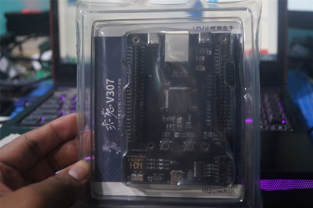
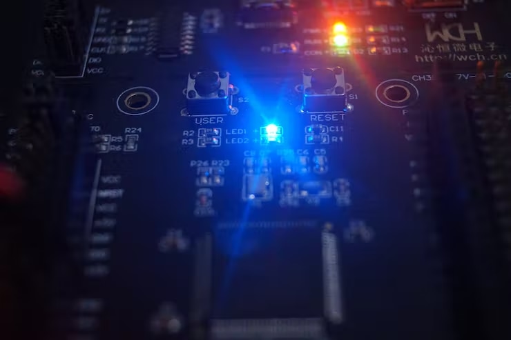
CH32V307 Development Board
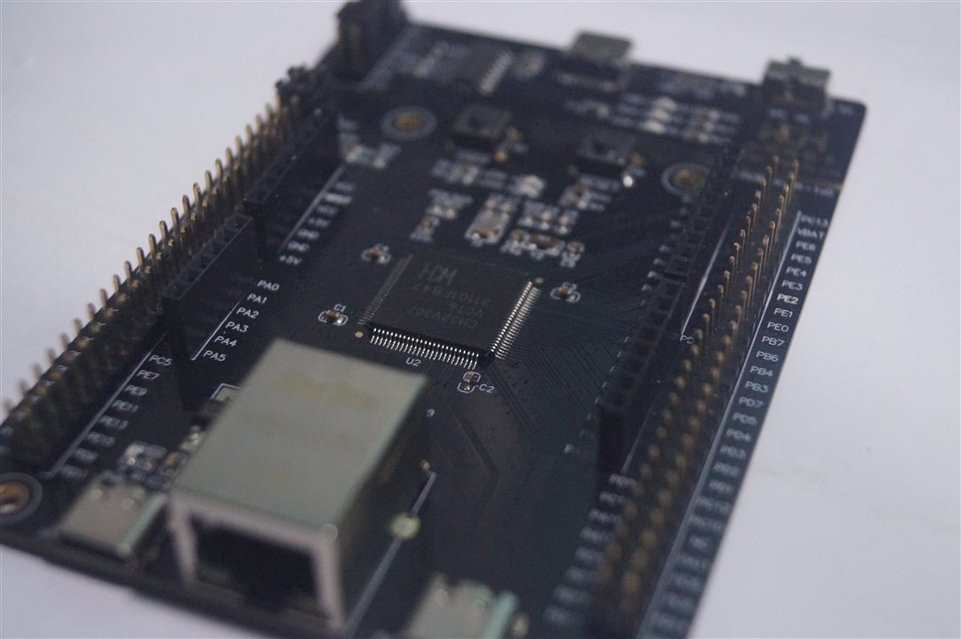
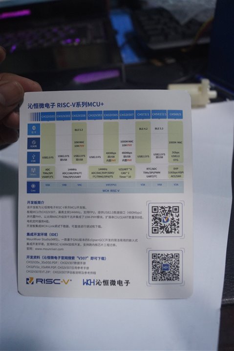
WCH designed RISC-V4F 32-bit RISC-V core up to 144MHz, supports Single-cycle multiplication and hardware division, and hardware float point unit (FPU). It has a memory of up to 64KB SRAM, Storage of Up to 256KB Flash.
This Development board has Networking – Gigabit Ethernet MAC, 10 Mbps PHY, USB – 1x USB 2.0 OTG full-speed interface, 1x USB 2.0 host/device interface with built-in 480 Mbps PHY, 8x USART, 2x CAN interfaces, 2-wire debug interface, SDIO, FSMC memory interface, DVP digital video interface, 80x GPIO ports, with 16 external interrupts, 2x I2C, 3x SPI, 2x I1S, 2x 12-bit DAC, 2-unit 16-channel 12-bit ADC, 16-channel TouchKey, 10 timers, 2x general DMA controllers, 18 channels in total, 4x amplifiers.
CH32V307 has Power management and is available in Packages: LQFP64M, andLQFP100.
HuskyLens
HuskyLens is an easy-to-use AI machine vision sensor. It is equipped with multiple functions, such as face recognition, object tracking, object recognition, line tracking, color recognition, and tag(QR code) recognition.
You can buy Husky Lens from https://www.dfrobot.com/product-1989.html?

Step 1: Getting Started with CH32V307
- First, we download the MounRiver Studio (MRS) using this link.
- Create a new Mounriver project, select CH32V307 [RISC-V] series, select RT-Thread in the template type and click finish.

Setting Up RT-Thread Studio
While working on the Mounriver IDE, I came across RT-Thread Studio that officially supports WCH Boards and other dev boards too. For that reason, I'll be using the RT-Thread Studio for this project hereafter.
- First, download the IDE from here and Install it on your PC.
- Open the RT-Thread SDK Manager and Install the CH32V307V-R1 under the WCH platform. This might take up some time.

- Once Installed, Create a new project. Name the file as LFR, Select the Board CH32v307V-R1 and RT-thread as latest. Click on the finish button.

- We write a basic program to toggle the built-in LED.
GPIO_ResetBits(GPIOA,GPIO_Pin_0);
	while(1)
	{
	    GPIO_SetBits(GPIOA,GPIO_Pin_0);
	    rt_thread_mdelay(500);
	    GPIO_ResetBits(GPIOA,GPIO_Pin_0);
	    rt_thread_mdelay(500);
	}
Step 2: Interfacing HuskyLens
- Update the firmware to the HUSKYLENSWithModelV0.4.9Class.kfpkg with K-Flash.

- Install the HUSKYLENS Library
First, download and install the HUSKYLENS Library first.
Copy the "HUSKYLENS" to our project directory as shown below

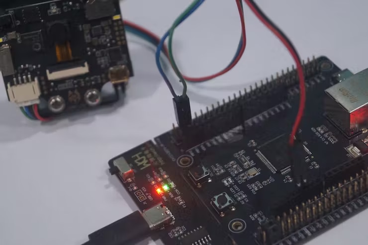
- Connection Diagram
The CH32V307 USART3 Pins are PB10 & PB11. These are used to communicate with HuskyLens.The L293D motor driver shield is connected to the Arduino Header as shown.
- CH32V307 -> HuskyLens
Vcc -> Vcc
GND -> GND
USART3_Tx(PB10) -> RX
USART3_Rx(PB11) -> TX

Make the connections mentioned above.
- Interfacing with Husky Lens
HuskyLens Protocol Setting You need to set the protocol type of HuskyLens. The protocol should be 'Serial 115200'. Of course, you can adopt the Auto Detect protocol, which is easy to use and convenient.

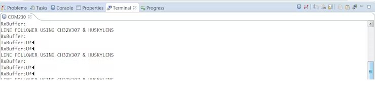
You can find the sample code below which is used to interface with the Huskylens.
int main(void)
{
	for(char s=0; s<TxSize; s++) {
		TxBuffer[s] = cmd1[s];
	}
	NVIC_PriorityGroupConfig(NVIC_PriorityGroup_2);
	Delay_Init();
	USART_Printf_Init(115200);
	printf("LINE FOLLOWER USING CH32V307 & HUSKYLENS\r\n");
	printf("RxBuffer:%s\r\n", RxBuffer);
	printf("TxBuffer:%s\r\n", TxBuffer);
        USARTx_CFG(); /* USART3 Initializes */

    while(TxCnt < TxSize) /* USART3--->USART2 */
       {
           USART_SendData(USART3, TxBuffer[TxCnt++]);
           while(USART_GetFlagStatus(USART3, USART_FLAG_TXE) == RESET); /* waiting for sending finish */
       }

    Delay_Ms(100);
    while(!Rxfinish); /* waiting for receiving int finish */
    printf("RxBuffer:%s\r\n", RxBuffer);

            while(1)
            {
            	while(TxCnt < TxSize) /* USART3--->USART2 */
            	       {
            	        USART_SendData(USART3, TxBuffer[TxCnt++]);
            	        while(USART_GetFlagStatus(USART3, USART_FLAG_TXE) == RESET) ;
            	       }

            	    Delay_Ms(1000);
            }
}
while (!huskylens.begin(USART3))
    {
    printf("Begin failed!\n");
    printf("1.Please recheck the \"Protocol Type\" in HUSKYLENS (General Settings>>Protocol Type>>Serial 9600)\n");
    printf("2.Please recheck the connection.\n");
    Delay_Ms(1000);
    }

    Delay_Ms(100);

    while(1)
    {
    	if (!huskylens.request()) printf("Fail to request data from HUSKYLENS, recheck the connection!");
    	else if(!huskylens.isLearned()) printf("Nothing learned, press learn button on HUSKYLENS to learn one!");
    	else if(!huskylens.available()) printf("No block or arrow appears on the screen!");
    	else
    	{
    	printf("###########");
		while(huskylens.available())
			{
			HUSKYLENSResult result = huskylens.read();
			printResult(result);
			}
    	}
    }
void printResult(HUSKYLENSResult result){
    if (result.command == COMMAND_RETURN_BLOCK){
        Serial.println(String()+F("Block:xCenter=")+result.xCenter+F(",yCenter=")+result.yCenter+F(",width=")+result.width+F(",height=")+result.height+F(",ID=")+result.ID);
    }
    else if (result.command == COMMAND_RETURN_ARROW){
        Serial.println(String()+F("Arrow:xOrigin=")+result.xOrigin+F(",yOrigin=")+result.yOrigin+F(",xTarget=")+result.xTarget+F(",yTarget=")+result.yTarget+F(",ID=")+result.ID);
    }
    else{
        Serial.println("Object unknown!");
    }
}
Operation and Setting
- Dial the function button to the left or right until the word "Line Tracking" is displayed at the top of the screen.
- Long press the function button to enter the parameter setting of the line tracking function.
- Dial the function button right or left until "Learn Multiple" is selected, then short press the function button, and dial it to the left to turn off the "Learn Multiple" switch, that is, the square icon on the progress bar is turned to the left. Then short press the function button to complete this parameter.
- You can also turn on the LEDs by setting "LED Switch". This is very useful in a dark environment.
- Dial the function button to the left until "Save & Return" is selected, and short press the function button to save the parameters and it will return automatically.
Line Learning: It is recommended that within the view field of HuskyLens, just remain inline to learn and have no cross lines. Point the "+" symbol at the line. Then HuskyLens will automatically detect the line and a white arrow will appear on the screen. At that time, short press the "learning button" to complete the learning process. A blue route direction arrow will appear on the screen.

Line Prediction: When HuskyLens detects the line which has been learned, a blue arrow will appear automatically on the screen. The direction of the arrow indicates the predicted direction of the line.

Now the device is ready for Line detection.

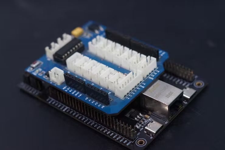
Step 3: Interfacing Motor Driver
Since the CH32V307 board has Arduino Compatible headers, I bought an L293D dual motor driver shield that can be easily plugged into the Dev board.
Motor Test is done using the following code.
/*
 * Pin PA8 and PA0 - Motor 1
 * Pin PB6 and PB8 - Motor 2
*/

u8 speed = 100; // -255 to +255
int main(void)
{
	USART_Printf_Init(115200);
	printf("Speed Control");
	TIM1_PWMOut_Init( 100, 48000-1, speed, speed); // fwd
        delay(5000);
	TIM1_PWMOut_Init( 100, 48000-1, -speed, -speed); // rev
	while(1);
}
Step 4: Block Diagram
The Complete connections can be done by following the block diagram and would look like this.

Step 5: Enclosure Design
I bought a standard Robot chassis from a local store for $4. We have the BO motors on the left and right sides of the Chassis and a ball caster for balancing weight.

Next, we mount the Husky Lens with the given L clamps and it turns like this.

Now we add the CH32V307 and the Motor driver to the chassis. I've got 2 Lithium-ion cells to run this robot. These cells are connected in series to provide 7.4V. This can be replaced with Li-Po batteries too.
Step 6: Let's See It Working
Finally, it's time to run the robot. I ran the HuskyLens sensor and serially printed the computed speed and this is what I got.

Although it is not a perfect line follower, by calibrating the PID constants, we can achieve smoother operation.
If you faced any issues in building this project, feel free to ask me. Please do suggest new projects that you want me to do next.
Give a thumbs up if it really helped you and do follow my channel for interesting projects. :)
Share this video if you like.
Github - https://github.com/Rahul24-06/
Happy to have you subscribed: https://www.youtube.com/c/rahulkhanna24june?sub_confirmation=1
Thanks for reading


