element14 Community
element14 Community
    Register Log In
  • Site
  • Search
  • Log In Register
  • About Us
  • Community Hub
    Community Hub
    • What's New on element14
    • Feedback and Support
    • Benefits of Membership
    • Personal Blogs
    • Members Area
    • Achievement Levels
  • Learn
    Learn
    • Ask an Expert
    • eBooks
    • element14 presents
    • Learning Center
    • Tech Spotlight
    • STEM Academy
    • Webinars, Training and Events
    • Learning Groups
  • Technologies
    Technologies
    • 3D Printing
    • FPGA
    • Industrial Automation
    • Internet of Things
    • Power & Energy
    • Sensors
    • Technology Groups
  • Challenges & Projects
    Challenges & Projects
    • Design Challenges
    • element14 presents Projects
    • Project14
    • Arduino Projects
    • Raspberry Pi Projects
    • Project Groups
  • Products
    Products
    • Arduino
    • Avnet Boards Community
    • Dev Tools
    • Manufacturers
    • Multicomp Pro
    • Product Groups
    • Raspberry Pi
    • RoadTests & Reviews
  • Store
    Store
    • Visit Your Store
    • Choose another store...
      • Europe
      •  Austria (German)
      •  Belgium (Dutch, French)
      •  Bulgaria (Bulgarian)
      •  Czech Republic (Czech)
      •  Denmark (Danish)
      •  Estonia (Estonian)
      •  Finland (Finnish)
      •  France (French)
      •  Germany (German)
      •  Hungary (Hungarian)
      •  Ireland
      •  Israel
      •  Italy (Italian)
      •  Latvia (Latvian)
      •  
      •  Lithuania (Lithuanian)
      •  Netherlands (Dutch)
      •  Norway (Norwegian)
      •  Poland (Polish)
      •  Portugal (Portuguese)
      •  Romania (Romanian)
      •  Russia (Russian)
      •  Slovakia (Slovak)
      •  Slovenia (Slovenian)
      •  Spain (Spanish)
      •  Sweden (Swedish)
      •  Switzerland(German, French)
      •  Turkey (Turkish)
      •  United Kingdom
      • Asia Pacific
      •  Australia
      •  China
      •  Hong Kong
      •  India
      •  Korea (Korean)
      •  Malaysia
      •  New Zealand
      •  Philippines
      •  Singapore
      •  Taiwan
      •  Thailand (Thai)
      • Americas
      •  Brazil (Portuguese)
      •  Canada
      •  Mexico (Spanish)
      •  United States
      Can't find the country/region you're looking for? Visit our export site or find a local distributor.
  • Translate
  • Profile
  • Settings
Enchanted Objects
  • Challenges & Projects
  • Design Challenges
  • Enchanted Objects
  • More
  • Cancel
Enchanted Objects
Blog Debuging the I2C to 1-Wire Bridge
  • Blog
  • Forum
  • Documents
  • Polls
  • Files
  • Events
  • Mentions
  • Sub-Groups
  • Tags
  • More
  • Cancel
  • New
  • Share
  • More
  • Cancel
Group Actions
  • Group RSS
  • More
  • Cancel
Engagement
  • Author Author: crjeder
  • Date Created: 26 Apr 2015 7:49 PM Date Created
  • Views 1386 views
  • Likes 4 likes
  • Comments 7 comments
  • smart_key_hooks
  • enchanted_objects
  • 1-wire
  • logic_analyzer
Related
Recommended

Debuging the I2C to 1-Wire Bridge

crjeder
crjeder
26 Apr 2015

I recognized that I tend to post only positive results but at the same time I learn a lot from the mistakes of others I decided to devote this blog to my time wasting effort of interfacing 1-Wire components from node.js. Several evenings I read blog post, documentation and code just to find out what I am doing wrong - with no result. It still did not work. Owfs was not able to detect the devices nor could the linux kernel show me the information in the /sys/bus/w1/ directory. I was a bit frustrating. I was about to order new components because I thought my first experience in SMD soldering went wrong. Today I went home a little early and spent the afternoon in my lab - despite the good weather. I used a logic sniffer to see what's going on. And this journey will be recorded in this blog post.

Setup


To eliminate as many unknowns from the equation I decided to test using my BeagleBone Black which I am more used to than the SAMA5D4.

image

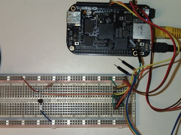
On the BBB the P9-19 and 20 are the I2C-1 which I am going to use. The DS2482-100's SDA and SCL are 3.3 V capable so they can be connected directly. The Linux configuration does not have to be changed since the I2C-1 is enabled by default. Connect the DS24B33 EEPROM and I am done! Right? First test it with i2cdetect:

i2cdetect -y -r 1
     0  1  2  3  4  5  6  7  8  9  a  b  c  d  e  f
00:          -- -- -- -- -- -- -- -- -- -- -- -- --
10: -- -- -- -- -- -- -- -- -- -- -- -- -- -- -- --
20: -- -- -- -- -- -- -- -- -- -- -- -- -- -- -- --
30: -- -- -- -- -- -- -- -- -- -- -- -- -- -- -- --
40: -- -- -- -- -- -- -- -- -- -- -- -- -- -- -- --
50: -- -- -- -- UU UU UU UU -- -- -- -- -- -- -- --
60: -- -- -- -- -- -- -- -- -- -- -- -- -- -- -- --
70: -- -- -- -- -- -- -- --

The i2c to 1-wire bridge should show up at address 0x18.

NO! It isn't that easy. Reading more documentation I got a few things to try: pull-up resistors for SDA and SCL, kernel modules to load and much more. And nothing helped. So I disconnected everything and connected it again but out of frustration I did not disconnect the BBB contrary to a omnipresent warning that you never should connect anything to the pin headers while the board is running. And this time i2cdetect showed:

i2cdetect -y -r 1
     0  1  2  3  4  5  6  7  8  9  a  b  c  d  e  f
00:          -- -- -- -- -- -- -- -- -- -- -- -- --
10: -- -- -- -- -- -- -- -- 18 -- -- -- -- -- -- --
20: -- -- -- -- -- -- -- -- -- -- -- -- -- -- -- --
30: -- -- -- -- -- -- -- -- -- -- -- -- -- -- -- --
40: -- -- -- -- -- -- -- -- -- -- -- -- -- -- -- --
50: -- -- -- -- UU UU UU UU -- -- -- -- -- -- -- --
60: -- -- -- -- -- -- -- -- -- -- -- -- -- -- -- --
70: -- -- -- -- -- -- -- --

Vola! At least the DS2482 was detected.

If the drivers were loaded correctly /sys/bus/w1/ would show something:

root@beaglebone:~# ls /sys/bus/w1/devices/
root@beaglebone:~#

Nothing!

Maybe the drivers are not loaded? Let's check:

root@beaglebone:~# lsmod
Module                  Size  Used by
g_multi                50407  2
libcomposite           15028  1 g_multi
mt7601Usta            641118  0
root@beaglebone:~#

To install them manually I tried:

root@beaglebone:~# modprobe ds1wm
root@beaglebone:~# modprobe ds2482
root@beaglebone:~# modprobe omap_hdq
root@beaglebone:~# modprobe w1_ds2433

Nothing changed. More frustration. Ok. Don't give up! What else can I try? Other software? Other hardware? Analyse what's going on on the bus?

I decided to do the later.


Logic Analyser


Fortunately I've bought a simple USB 8-channel logic analyzer a while ago. Never used it seriously, though. Looks like is time again to learn something new. I have taped the SDA and SDL pins to see if the DS2482 works correctly. I already could verify that it is listening on address 0x18.

image

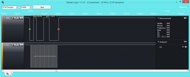
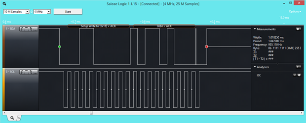
The first action on the bus is not a surprise - we see a write to address 0x18 (the address of the bus master) and then the byte 0xF0 which is the command "Device Reset". Good.

image

I had not expected to see the read from address 0x18, but reading the data sheet I found the recommendation to read the status register to verify if the reset was performed. After reset the read pointer points to the status register, therefore a simple read will result in the value of the status register. Here it is 0x18 or in binary 0b00011000. The status register bits are DIR-TSB-SBR-RST-LL-SD-PPD-1WB where:

Bit NameDescripiton
DIRBranch Direction Taken
TSBTriplet Second Bit
SBRSingle Bit Result
RSTDevice Reset: Reset has been performed.
LLLogic Level: Reads the logic state of the 1-Wire bus without initialising a communication. Updated on every read
SDShort Detected: Updated on every 1-Wire command.
PPDPresence Pulse Detect: Set when a presence detect pulse is seen by the bus master. Updated on every reset.
1WB1-Wire Busy: reports if the bus is currently in use.

The three most significant bits are for data transfer on the 1-wire bus, the others are real status bits. In this case the RST and LL are set which means the reset was performed and the 1-Wire bus is in "high" state.

image

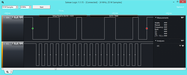
Then the next command is written to the I2C bus: 0xE1 (Set Read Pointer) 0xF0 (Status Register). So the next command has to be a read. It resulted in 0x18, the same as above.

image

This time 0xB4 is written to the DS2482. This is the command for 1-Wire reset.

image

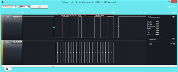
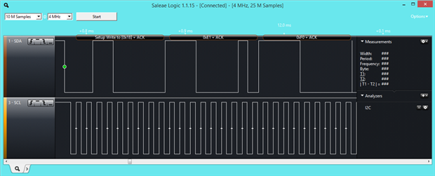
The status register is read again, but this time the result is 0x19 so the least significant bit has changed to "high" which means the 1-Wire bus is busy. The host has to wait until the command has finished. The next read returned 0x18, again. The reset was completed but no presence pulse detected. That's why I could not access any 1-Wire devices. But why? I checked the whole circuit and found two really stupid mistakes: on the 1 wire eeprom (DS24B33) the ground pin was connected to the 3V3 pin and the pull-up resistor's bands had the colours red-red-brown which is 220 Ω. The data sheet says Rpullup should be between 0.3 and 2.2 kΩ. I looked for a red-red-red labelled resistor and installed it instead. This time I got this result:

image

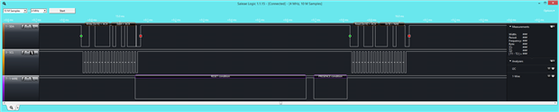
Finally there is the Presence Detect Pulse!  The rest of the communication read the 1-Wire ID form the DS24B33. Now the key identification works.


Conclusion


I used a quite advanced tool to find a set of very stupid mistakes which a more experienced person would have detected on the first sight or would not have made at all.

But on the Pro side I learned how to use a quite handy tool and a lot about I2C and 1-Wire bus. Since the competition is about learning this goal was meat. For the other goals I really have to catch up now.

  • Sign in to reply

Top Comments

  • crjeder
    crjeder over 10 years ago in reply to Workshopshed +3
    My budget for tools is also limited but saleae and Bus Blaster are well below $/€ 50. So I think they are a good investment. The old saleae I have is without analog and therefore cheaper (look at ebay…
  • Jan Cumps
    Jan Cumps over 10 years ago in reply to Workshopshed +2
    I'm using a Papilio FPGA board with open source client as LA / protocol analyzer. For the typical serial protocols, this works rather well - up to 32 channels. That way I have two things in 1: an FPGA…
  • DAB
    DAB over 10 years ago +1
    Very good post. Trust me, we all learn much more from failures than we do first time successes. You did a good job of investigating the problem, you used a good tool to help resolve the issues and in the…
  • crjeder
    crjeder over 10 years ago in reply to Workshopshed

    My budget for tools is also limited but saleae and Bus Blaster are well below $/€ 50. So I think they are a good investment. The old saleae I have is without analog and therefore cheaper (look at ebay or amazon to find good deals).


    Does anybody know a USB connected oscilloscope in this price range?


    Thanks!

    • Cancel
    • Vote Up +3 Vote Down
    • Sign in to reply
    • More
    • Cancel
  • mcb1
    mcb1 over 10 years ago

    Great post with the methods used to verify the problem.


    As the others said sometimes the failures are our greatest learning ...image


    Mark

    • Cancel
    • Vote Up 0 Vote Down
    • Sign in to reply
    • More
    • Cancel
  • Jan Cumps
    Jan Cumps over 10 years ago in reply to Workshopshed

    I'm using a Papilio FPGA board with open source client as LA / protocol analyzer.

    For the typical serial protocols, this works rather well - up to 32 channels.

    That way I have two things in 1: an FPGA dev kit and a la. That makes the purchase a bit sweeter.


    Make a Logic Analyzer from your Dev Kit Part 2: Papilio FPGA

    • Cancel
    • Vote Up +2 Vote Down
    • Sign in to reply
    • More
    • Cancel
  • clem57
    clem57 over 10 years ago

    Great way to learn. Nice blogging too.

    Clem

    • Cancel
    • Vote Up 0 Vote Down
    • Sign in to reply
    • More
    • Cancel
  • Workshopshed
    Workshopshed over 10 years ago

    I agree, I've learnt a lot more by failing that I would have done if everything had worked. That logic analyser looks good. I'm afraid my instrumentation is limited to a multi-meter, some moving coil meters, LEDs and whatever I can fashion using Arduinos.

    • Cancel
    • Vote Up 0 Vote Down
    • Sign in to reply
    • More
    • Cancel
>
element14 Community

element14 is the first online community specifically for engineers. Connect with your peers and get expert answers to your questions.

  • Members
  • Learn
  • Technologies
  • Challenges & Projects
  • Products
  • Store
  • About Us
  • Feedback & Support
  • FAQs
  • Terms of Use
  • Privacy Policy
  • Legal and Copyright Notices
  • Sitemap
  • Cookies

An Avnet Company © 2025 Premier Farnell Limited. All Rights Reserved.

Premier Farnell Ltd, registered in England and Wales (no 00876412), registered office: Farnell House, Forge Lane, Leeds LS12 2NE.

ICP 备案号 10220084.

Follow element14

  • X
  • Facebook
  • linkedin
  • YouTube