element14 Community
element14 Community
    Register Log In
  • Site
  • Search
  • Log In Register
  • About Us
  • Community Hub
    Community Hub
    • What's New on element14
    • Feedback and Support
    • Benefits of Membership
    • Personal Blogs
    • Members Area
    • Achievement Levels
  • Learn
    Learn
    • Ask an Expert
    • eBooks
    • element14 presents
    • Learning Center
    • Tech Spotlight
    • STEM Academy
    • Webinars, Training and Events
    • Learning Groups
  • Technologies
    Technologies
    • 3D Printing
    • FPGA
    • Industrial Automation
    • Internet of Things
    • Power & Energy
    • Sensors
    • Technology Groups
  • Challenges & Projects
    Challenges & Projects
    • Design Challenges
    • element14 presents Projects
    • Project14
    • Arduino Projects
    • Raspberry Pi Projects
    • Project Groups
  • Products
    Products
    • Arduino
    • Avnet Boards Community
    • Dev Tools
    • Manufacturers
    • Multicomp Pro
    • Product Groups
    • Raspberry Pi
    • RoadTests & Reviews
  • Store
    Store
    • Visit Your Store
    • Choose another store...
      • Europe
      •  Austria (German)
      •  Belgium (Dutch, French)
      •  Bulgaria (Bulgarian)
      •  Czech Republic (Czech)
      •  Denmark (Danish)
      •  Estonia (Estonian)
      •  Finland (Finnish)
      •  France (French)
      •  Germany (German)
      •  Hungary (Hungarian)
      •  Ireland
      •  Israel
      •  Italy (Italian)
      •  Latvia (Latvian)
      •  
      •  Lithuania (Lithuanian)
      •  Netherlands (Dutch)
      •  Norway (Norwegian)
      •  Poland (Polish)
      •  Portugal (Portuguese)
      •  Romania (Romanian)
      •  Russia (Russian)
      •  Slovakia (Slovak)
      •  Slovenia (Slovenian)
      •  Spain (Spanish)
      •  Sweden (Swedish)
      •  Switzerland(German, French)
      •  Turkey (Turkish)
      •  United Kingdom
      • Asia Pacific
      •  Australia
      •  China
      •  Hong Kong
      •  India
      •  Korea (Korean)
      •  Malaysia
      •  New Zealand
      •  Philippines
      •  Singapore
      •  Taiwan
      •  Thailand (Thai)
      • Americas
      •  Brazil (Portuguese)
      •  Canada
      •  Mexico (Spanish)
      •  United States
      Can't find the country/region you're looking for? Visit our export site or find a local distributor.
  • Translate
  • Profile
  • Settings
Enchanted Objects
  • Challenges & Projects
  • Design Challenges
  • Enchanted Objects
  • More
  • Cancel
Enchanted Objects
Blog Generating a Mysterious Signal
  • Blog
  • Forum
  • Documents
  • Polls
  • Files
  • Events
  • Mentions
  • Sub-Groups
  • Tags
  • More
  • Cancel
  • New
  • Share
  • More
  • Cancel
Group Actions
  • Group RSS
  • More
  • Cancel
Engagement
  • Author Author: crjeder
  • Date Created: 7 Jun 2015 10:23 PM Date Created
  • Views 3530 views
  • Likes 4 likes
  • Comments 46 comments
  • smart_key_hooks
  • enchanted_objects
  • bit_banging
Related
Recommended

Generating a Mysterious Signal

crjeder
crjeder
7 Jun 2015

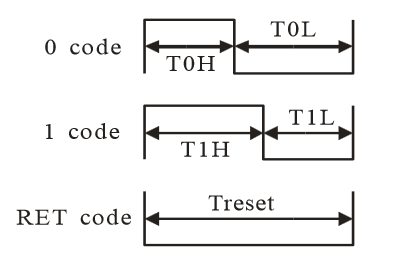
Let us assume that I want to create a signal like this:


image

Where:


Signal

Name

Duration in

μs ± 150 ns

T0H0.4
T1H0.8
T0L0.85
T1L0.45
Treset> 50


The usual way to generate arbitrary signals is called "Bit banging". It requires software to set the output in the "HIGH" and "LOW" state in the exact timing given by the protocol. The timing requirements for this signal look pretty strict that I do not believe that this would be possible or at least not very reliable. So I am looking for some hardware support.

After a lot of head ache and reading datasheets the idea of using the PWM came into my mind.

Bit Banging with PWM


Let's look at the signal again:

  • it starts always with "HIGH" and ends with "LOW" (except for reset which is always "LOW")
  • length of signal is 1.25 μs (reset again an exception)
  • 0.05 μs resolution (0.05 is the greatest common divisor of 1.25, 0.4, 0.85 and 0.45)


Exact Solution

The signal can be generated with PWM of 1/0.05 μs = 20 MHz frequency. Therefore the "alphabet" above translates to:


SymbolDuty %
"0"32
"1"64


The PWM frequency of 20 MHz is quite high, can the signal be done approximated with lower frequency?


Reasonable Approximation

The odd thing about the spec for this signal is that it is not symmetric, i. E. the high time for "0" is not equal to the low time for "1" as I had expected. Since the rising edge of the signal is every 1.25 μs this allows the receiver to synchronize. The sampling presumably takes place at exactly the half of the time which explains the asymmetry: It gives a safety margin for the timing or rather does not require steep edges.

The tolerance for the falling edge is quite high. I did not recognize it at first sight, but when I converted the whole timing into nano seconds (ns) It's pretty clear:


Signal Name

Time of Falling Edge

Nominal [ns]

Time of Falling Edge

Minimal [ns]

Time of Falling Edge

Maximal [ns]

T0H400350550
T1H800650950


This allows a much more reasonable approach:

Divide the 125 ns in three sections ad vary the duty cycle between 1/3 and 2/3 or in decimal:


SymbolDuty %
"0"33
"1"66


The frequency in this case is only 2.4 MHz. That's much better!


Reset


The reset symbol is an exception - it does not fit in the above timing. It can be generated by 40 periods with a duty cycle of 0%.

Since we are able to generate the signal there is only one question left: What is this for?


Usage of the Signal


Did you recognize / guess the signal? What do you think it is for? image


(solution in the next blog post)

  • Sign in to reply

Top Comments

  • crjeder
    crjeder over 10 years ago in reply to balearicdynamics +3
    Yes, the quiz with you guys balearicdynamics , mcb1 , clem57 and Workshopshed was a lot of fun! Thank you for participating!
  • Workshopshed
    Workshopshed over 10 years ago +2
    Will there be a small flower dancing along to the music?
  • mcb1
    mcb1 over 10 years ago in reply to crjeder +2
    It's been a very interesting trip back down memory lane... Looking at this sheet for WS2812B it says single NRZ protocol http://www.seeedstudio.com/document/pdf/WS2812B%20Datasheet.pdf There is some interesting…
  • mcb1
    mcb1 over 10 years ago in reply to crjeder

    Not to be picky, but I think your scaling for the mystery signal is incorrect.

    For a 1 on your raw signal the 'mystery signal' does a high and low which together = 125uS (which could be the clock cycle).


    If you excuse the poor cut and pasting, it should look more like this.

    image


    Mark

    • Cancel
    • Vote Up +2 Vote Down
    • Sign in to reply
    • More
    • Cancel
  • crjeder
    crjeder over 10 years ago in reply to mcb1

    mcb1 wrote:


    After counting 24 bits of data, it shapes any incoming and passes anything on the Data_In to the Data_Out pin.

    I'm presuming it also sends the reset to the next pixel ...

    The reset signal is used to set the LED from "pass the data" into "put next 24 bits into latch" mode. 

    • Cancel
    • Vote Up +1 Vote Down
    • Sign in to reply
    • More
    • Cancel
  • mcb1
    mcb1 over 10 years ago in reply to crjeder

    As far as I'm aware, NRZ is not about the voltage levels, its about data.


    I know from playing with these leds that you do require to have the right frequency for data, so here's what I believe is happening.

    Inside is an intelligent chip, that samples incoming data stream.


    They could either compare the data level against a counter to see if it is One or Zero, or just check the level at 1/2 way (ie 62.5uS)


    After counting 24 bits of data, it shapes any incoming and passes anything on the Data_In to the Data_Out pin.

    I'm presuming it also sends the reset to the next pixel ...


    Whatever you set these to will remain when you pull the data line, so you can just run once and then stop the processor if you want.


    Using PWM and setting the ratio is a very clever way to simulate what you need, so well done.

    You've also exercised many grey matters ....


    Mark

    • Cancel
    • Vote Up +1 Vote Down
    • Sign in to reply
    • More
    • Cancel
  • crjeder
    crjeder over 10 years ago in reply to balearicdynamics

    Yes, the quiz with you guys balearicdynamics, mcb1, clem57 and Workshopshed was a lot of fun! Thank you for participating!

    • Cancel
    • Vote Up +3 Vote Down
    • Sign in to reply
    • More
    • Cancel
  • balearicdynamics
    balearicdynamics over 10 years ago in reply to crjeder

    Sure, nothing to say about your solution, that I think it is the more elegant and simple. But ... Just to know thanks to your quiz more about this protocol, recovered from the memory lane image

    • Cancel
    • Vote Up 0 Vote Down
    • Sign in to reply
    • More
    • Cancel
>
element14 Community

element14 is the first online community specifically for engineers. Connect with your peers and get expert answers to your questions.

  • Members
  • Learn
  • Technologies
  • Challenges & Projects
  • Products
  • Store
  • About Us
  • Feedback & Support
  • FAQs
  • Terms of Use
  • Privacy Policy
  • Legal and Copyright Notices
  • Sitemap
  • Cookies

An Avnet Company © 2025 Premier Farnell Limited. All Rights Reserved.

Premier Farnell Ltd, registered in England and Wales (no 00876412), registered office: Farnell House, Forge Lane, Leeds LS12 2NE.

ICP 备案号 10220084.

Follow element14

  • X
  • Facebook
  • linkedin
  • YouTube