


For measuring body temperature, I need a sensor with a 0.1 °C accuracy (i.e. the accuracy you typically have in a thermometer).
Unfortunately, the sensor I initially thought of (the Melexis 96104 Infrared thermometer) does not match this requirement, neither do any of the other Infrared thermometer available on the market.
The main advantage of a infrared thermometer is that it can make measurements without the need to put the sensor in contact with the skin. Because of this lack of accuracy, I have to switch to a standard temperature sensor. After some researches, I found the TSic 506 sensor. The most interesting features of this sensor are
- it has an accuracy of 0.1 °C (and the best precision is reached at 40 °C, which is good when you have to measure body temperature)
- it does not require calibration
- it has a digital output, which simplifies the circuit because there is no need for and external signal conditioning logic
ZACwire protocol
The output is sent out using a very simple protocol: the ZACwire protocol. These are the protocol rules
- Each byte has a standard format: a start bit, 8 data bits and a parity bit.

- The output signal is normally high.
- Each bit transmission starts with a falling edge.
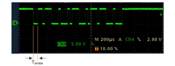
- A bit is a "0" or a "1" depending on the amount of time the output stays low. To determine whether a bit is "0" or "1", the time the signals stays needs to e compared with the low time of the start bit (commonly referred as TStrobe)

- The parity bit provides error detection by adding an even parity bit. This means that if the number of "1" bits in the 9 packet bits (8 data bits + 1 parity bit) has to be even
There is a ZACwire library available on the Arduino playground, but it uses a polling technique. Basically it stays stuck in a loop reading the digital input pin. I decided to improve a little bit this library by implementig the ZACwire protocol using the Input Capture capabilities available on Arduino Yun
Some background
A timer is a piece of hardware built in the Arduino controller. It is like a clock, and can be used to measure time events.
The Arduino Yun board is based on the Atmel AVR ATmega328 microchip. It has 3 timers, called Timer0, Timer1 and Timer2. Timer0 and Timer2 are 8bit timer, where Timer1 is a 16bit timer.
The most important difference between 8bit and 16bit timer is the timer resolution. 8bits means 256 values (two to the power of 8) where 16bit means 65536 values (two to the power of 16) which is much higher resolution.
All timers depends on the system clock of your Arduino system. Normally the system clock is 16MHz, but the Arduino Pro 3/3V is 8Mhz, so be careful when writing your own timer functions.
The timer hardware can be configured with some special timer registers. In the Arduino firmware, all timers were configured to a 1kHz frequency and interrupts are generally enabled. From our point of view, the most important timer-related registers are the following
- TCCRx - Timer/Counter Control Register. The pre-scaler can be configured here.
- TCNTx - Timer/Counter Register. The actual timer value is stored here.
- OCRx - Output Compare Register
- ICRx - Input Capture Register (only for 16bit timer)
- TIMSKx - Timer/Counter Interrupt Mask Register. To enable/disable timer interrupts.
- TIFRx - Timer/Counter Interrupt Flag Register. Indicates a pending timer interrupt.
The program running on a controller is normally running sequentially instruction by instruction. An interrupt is an external event that interrupts the running program and runs a special interrupt service routine (ISR). After the ISR has been finished, the running program is continued with the next instruction. Instruction means a single machine instruction, not a line of C or C++ code.
Before an pending interrupt will be able to call a ISR the following conditions must be true:
- Interrupts must be generally enabled
- the according Interrupt mask must be enabled
Interrupts can generally enabled or disabled with the function interrupts() ornoInterrupts(). By default in the Arduino firmware interrupts are enabled. Interrupt masks are enabled / disabled by setting or clearing bits in the Interrupt mask register (TIMSKx).
When an interrupt occurs, a flag in the interrupt flag register (TIFRx) is been set. This interrupt will be automatically cleared when entering the ISR or by manually clearing the bit in the interrupt flag register.
The Arduino functions attachInterrupt() and detachInterrupt() can only be used for external interrupt pins. These are different interrupt sources, not discussed here, and cannot be used for input capture interrupts
A timer can generate different types of interrupts.
- Timer Overflow:Timer overflow means the timer has reached is limit value. When a timer overflow interrupt occurs, the timer overflow bit TOVx will be set in the interrupt flag register TIFRx. When the timer overflow interrupt enable bit TOIEx in the interrupt mask register TIMSKx is set, the timer overflow interrupt service routine ISR(TIMERx_OVF_vect) will be called.
- Output Compare Match: When a output compare match interrupt occurs, the OCFxy flag will be set in the interrupt flag register TIFRx . When the output compare interrupt enable bit OCIExy in the interrupt mask register TIMSKx is set, the output compare match interrupt service ISR(TIMERx_COMPy_vect) routine will be called.
- Timer Input Capture: When a timer input capture interrupt occurs, the input capture flag bit ICFx will be set in the interrupt flag register TIFRx. When the input capture interrupt enable bit ICIEx in the interrupt mask register TIMSKx is set, the timer input capture interrupt service routine ISR(TIMERx_CAPT_vect) will be called.
The latter what we will leverage for implementing the ZACwire protocol
Let's start coding
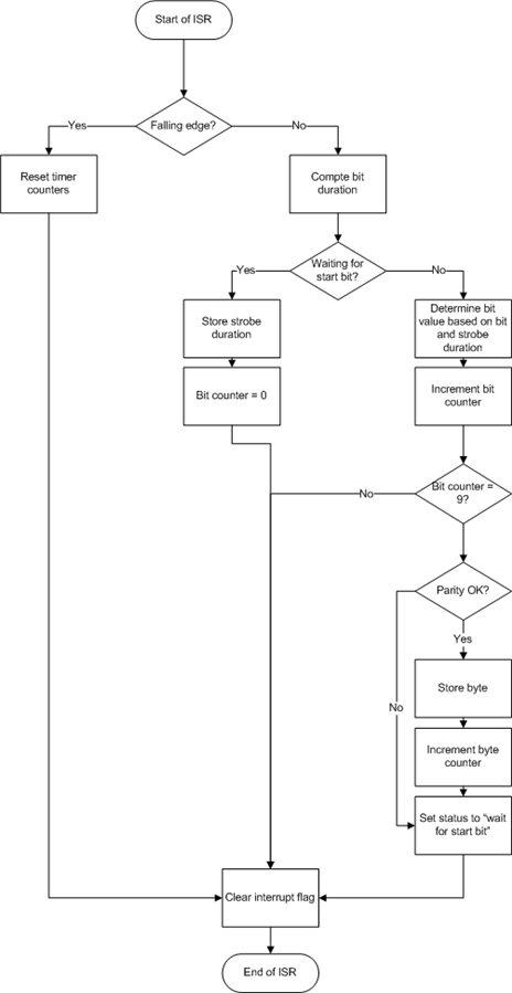
Flowchart below depicts the ISR routine is going to be implemented
Defining the Input Capture ISR routine is quite simple: just add a function like this
ISR(TIMER1_CAPT_vect) {
 // ISR code here
 }
But first of all, we need to properly setup Input Capture hardware
       // Input Capture setup
       // ICNC1: Enable Input Capture Noise Canceler
       // ICES1: =1 for trigger on rising edge (in this case we are interested
       //           in the falling edge
       // CS10: =1 set prescaler to 1x system clock (F_CPU)
       TCCR1A = 0;
       TCCR1B = (0<<ICNC1) | (0<<ICES1) | (1<<CS10);
       TCCR1C = 0;

       // Interrupt setup
       // ICIE1: Input capture
       // TOIE1: Timer1 overflow
       TIFR1 = (1<<ICF1) | (1<<TOV1);          // clear pending
       TIMSK1 = (1<<ICIE1) | (1<<TOIE1); // and enable
Once the timer has been initialized, we can start implementing the ISR routine
We will use an helper variable (rising) to determine whether we are catching a rising or a falling edge and a bunch of static variables to store ISR's state machine current status
byte waitingForStartBit = 1;
byte rising = 0;
byte bitCounter = 0;
int currByte = 0;
byte byteCounter = 0;
byte bytes[10];
byte bytesReady = 0;
byte expectedBytes = 2;
int tStrobe;
The implementation of the ISR method is a simple porting of the flowchart
ISR(TIMER1_CAPT_vect) {
       byte l = ICR1L;            // grab captured timer value
       byte h = ICR1H;
       int pulse;

       if (rising)
       {
             // rising edge
             if (waitingForStartBit)
             {
                    // store strobe duration
                    tStrobe = (h << 8) + l;

                    // reset status variables
                    waitingForStartBit = 0;
                    bitCounter = 0;
                    currByte = 0;
             }
             else
             {
                    // compute pulse duration
                    pulse = (h << 8) + l;

                    // append new bit
                    currByte <<= 1;
                    if (pulse >= (tStrobe * 3) / 4))
                           currByte |= 0x01;

                    bitCounter ++;
                    if (bitCounter == 9)
                    {
                           // all bits (including parity bits) read
                           if (checkParity(currByte))
                           {
                                  // remove parity bit
                                  currByte >>= 1;

                                  // enqueue byte
                                  bytes[byteCounter] = currByte;

                                  // increment byte counter
                                  byteCounter ++;
                                  if (byteCounter >= expectedBytes)
                                  {
                                        // no more bytes to read: disable interrupts
                                         TIMSK1 &= ~((1<<ICIE1) | (1<<TOIE1));
                                        bytesReady = 1;
                                  }
                           }

                           // start waiting for start bit of the next byte
                           waitingForStartBit = 1;
                    }
             }

             // set falling edge interrupt
             TCCR1B &= ~(1<<ICES1);
             rising = 0;
       }
       else
       {
             // falling edge
             // set rising edge interrupt
             TCCR1B |= (1<<ICES1);
             rising = 1;
       }
}
When temperature has to be read out from the TSic sensor, user will call a function like this
void getTemperature()
{
       waitingForStartBit = 1;
       rising = 0;
       bitCounter = 0;
       currByte = 0;
       byteCounter = 0;
       bytesReady = 0;
       expectedBytes = 2;

       // switch on TSic sensor
       // TODO

       initTimer();
}
and, in the main loop, will periodically check to see if the bytesReady variable has been set to 1. When bytesReady is 1, data in the bytes array can be converted to the actual temperature according to the formula (from TSic datasheet)
int sensorValue = (bytes[0] << 8) + bytes[1];
float celsius = ( (float)sensorValue/ 2047 * 7000) - 1000;
where celsius stores the current temperature value (in Celsius) multplied by 10
Top Comments