element14 Community
element14 Community
    Register Log In
  • Site
  • Search
  • Log In Register
  • About Us
  • Community Hub
    Community Hub
    • What's New on element14
    • Feedback and Support
    • Benefits of Membership
    • Personal Blogs
    • Members Area
    • Achievement Levels
  • Learn
    Learn
    • Ask an Expert
    • eBooks
    • element14 presents
    • Learning Center
    • Tech Spotlight
    • STEM Academy
    • Webinars, Training and Events
    • Learning Groups
  • Technologies
    Technologies
    • 3D Printing
    • FPGA
    • Industrial Automation
    • Internet of Things
    • Power & Energy
    • Sensors
    • Technology Groups
  • Challenges & Projects
    Challenges & Projects
    • Design Challenges
    • element14 presents Projects
    • Project14
    • Arduino Projects
    • Raspberry Pi Projects
    • Project Groups
  • Products
    Products
    • Arduino
    • Avnet Boards Community
    • Dev Tools
    • Manufacturers
    • Multicomp Pro
    • Product Groups
    • Raspberry Pi
    • RoadTests & Reviews
  • Store
    Store
    • Visit Your Store
    • Choose another store...
      • Europe
      •  Austria (German)
      •  Belgium (Dutch, French)
      •  Bulgaria (Bulgarian)
      •  Czech Republic (Czech)
      •  Denmark (Danish)
      •  Estonia (Estonian)
      •  Finland (Finnish)
      •  France (French)
      •  Germany (German)
      •  Hungary (Hungarian)
      •  Ireland
      •  Israel
      •  Italy (Italian)
      •  Latvia (Latvian)
      •  
      •  Lithuania (Lithuanian)
      •  Netherlands (Dutch)
      •  Norway (Norwegian)
      •  Poland (Polish)
      •  Portugal (Portuguese)
      •  Romania (Romanian)
      •  Russia (Russian)
      •  Slovakia (Slovak)
      •  Slovenia (Slovenian)
      •  Spain (Spanish)
      •  Sweden (Swedish)
      •  Switzerland(German, French)
      •  Turkey (Turkish)
      •  United Kingdom
      • Asia Pacific
      •  Australia
      •  China
      •  Hong Kong
      •  India
      •  Korea (Korean)
      •  Malaysia
      •  New Zealand
      •  Philippines
      •  Singapore
      •  Taiwan
      •  Thailand (Thai)
      • Americas
      •  Brazil (Portuguese)
      •  Canada
      •  Mexico (Spanish)
      •  United States
      Can't find the country/region you're looking for? Visit our export site or find a local distributor.
  • Translate
  • Profile
  • Settings
Enchanted Objects
  • Challenges & Projects
  • Design Challenges
  • Enchanted Objects
  • More
  • Cancel
Enchanted Objects
Blog MagicHat - 4 - Heart beat sensor
  • Blog
  • Forum
  • Documents
  • Polls
  • Files
  • Events
  • Mentions
  • Sub-Groups
  • Tags
  • More
  • Cancel
  • New
  • Share
  • More
  • Cancel
Group Actions
  • Group RSS
  • More
  • Cancel
Engagement
  • Author Author: amgalbu
  • Date Created: 30 Mar 2015 7:37 AM Date Created
  • Views 1336 views
  • Likes 8 likes
  • Comments 7 comments
  • heartbeat
  • enchanted_objects
  • opamps
  • heart-rate
  • magic_doctor_hat
Related
Recommended

MagicHat - 4 - Heart beat sensor

amgalbu
amgalbu
30 Mar 2015

One of the most challenging part of this project is to measure the heart beat (and then blood pressure)

Hear beat measuring is based on the principle of photoplethysmography (PPG) which is a non-invasive method of measuring the variation in blood volume in tissues using a light source and a detector. Since the change in blood volume is synchronous to the heart beat, this technique can be used to calculate the heart rate. Transmittance and reflectance are two basic types of photoplethysmography. For the transmittance PPG, a light source is emitted in to the tissue and a light detector is placed in the opposite side of the tissue to measure the resultant light. Because of the limited penetration depth of the light through organ tissue, the transmittance PPG is applicable to a restricted body part, such as the finger or the ear lobe. However, in the reflectance PPG, the light source and the light detector are both placed on the same side of a body part. The light is emitted into the tissue and the reflected light is measured by the detector. As the light doesn’t have to penetrate the body, the reflectance PPG can be applied to any parts of human body. In either case, the detected light reflected from or transmitted through the body part will fluctuate according to the pulsatile blood flow caused by the beating of the heart.

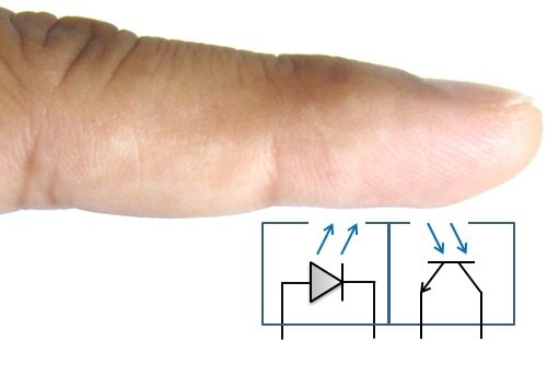
The following picture shows a basic reflectance PPG probe to extract the pulse signal from the fingertip. A subject’s finger is illuminated by an infrared light-emitting diode. More or less light is absorbed, depending on the tissue blood volume. Consequently, the reflected light intensity varies with the pulsing of the blood with heart beat. A plot for this variation against time is referred to be a photoplethysmographic or PPG signal.


image


The PPG signal has two components, frequently referred to as AC and DC. The AC component is mainly caused by pulsatile changes in arterial blood volume, which is synchronous with the heart beat. So, the AC component can be used as a source of heart rate information. This AC component is superimposed onto a large DC component that relates to the tissues and to the average blood volume. The DC component must be removed to measure the AC waveform with a high signal-to-noise ratio. Since the useful AC signal is only a very small portion of the whole signal, an effective amplification circuit is also required to extract desired information from it.


A very useful source of information was this one, where I got most of the information I need to build a heart rate sensor.


However, I decided to make some changes to the original design to use a different light sensor: the TCRT1000. This is a reflective optical sensor with both the infrared light emitter and phototransistor placed side by side and are enclosed inside a leaded package so that there is minimum effect of surrounding visible light. The circuit diagram below shows the external biasing circuit for the TCRT1000 sensor.


image


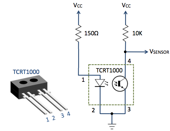
A fingertip placed over the sensor will act as a reflector of the incident light. The amount of light reflected back from the fingertip is monitored by the phototransistor.

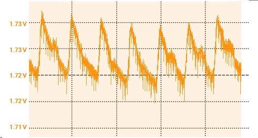
The output (VSENSOR) from the sensor is a periodic physiological waveform attributed to small variations in the reflected IR light which is caused by the pulsatile tissue blood volume inside the finger. The waveform is, therefore, synchronous with the heart beat. The following circuit diagram describes the first stage of the signal conditioning which will suppress the large DC component and boost the weak pulsatile AC component, which carries the required information.


image


The starting point for my experiments will be an adaptation of the original schematic of the Pulse Sensor module


image


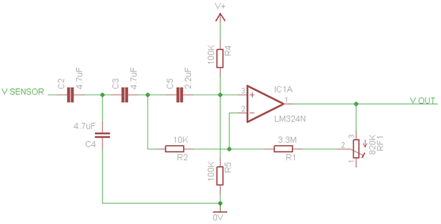
The basic idea is that the operational amplifier sums up Vcc/2 with the amplified DC component of the Vsensor

Vcc/2 is obtained through the R4/R5 partitor. The AC component is measured on the C5 capacitor. This signal is amplified by a factor of 330 (R1/R2). The RF1 trimmer will make it possible to fine-tune the gain

  • Sign in to reply

Top Comments

  • mcb1
    mcb1 over 10 years ago +1
    Looks great. If this doesn't work, let me know as I have a circuit we used in disco lighting equipment to adjust the gain, but respond to the bass pulses. I'm sure it could be adapted to give a potentially…
  • amgalbu
    amgalbu over 10 years ago in reply to crjeder

    I am i difficult in selecting to most suitable solution... I hope I made the right choice!
    Again thanks for you feedback


    cheers

    • Cancel
    • Vote Up 0 Vote Down
    • Sign in to reply
    • More
    • Cancel
  • crjeder
    crjeder over 10 years ago in reply to amgalbu

    Jep. I haven't researched into the problem and don't know if the solutions are any better. Just let you know just in case.

    I'll follow your post 'cause I am interested in sensors in general and blood pressure and heart beat in particular. Maybe that will be one of my next projects?

    Thank you for the detailed posts!

    • Cancel
    • Vote Up 0 Vote Down
    • Sign in to reply
    • More
    • Cancel
  • amgalbu
    amgalbu over 10 years ago in reply to crjeder

    Hi crjeder

    Thanks for your suggestions!

    I'm aware there are many possible approaches to the problem. I chose this option mainly for two reasons

    1. the sensor is very cheap (0.8 euros)

    2. it provides a good accuracy to measure blood pressure as well (the hack with the piezo electric is ok for heart rate only)


    Cheers

    • Cancel
    • Vote Up 0 Vote Down
    • Sign in to reply
    • More
    • Cancel
  • crjeder
    crjeder over 10 years ago

    An other nice idea is what I found at Hackaday: Measuring Heart Rate With A Piezo | Hackaday

    And I am wondering if IR is the right wave length because some smart wathches use green light because it can penedrate the skin, as far as I remember.

    Found something while I was looking for a reference:

    Compact Osram sensor improves fitness monitoring | OSRAM Opto Semiconductors

    • Cancel
    • Vote Up 0 Vote Down
    • Sign in to reply
    • More
    • Cancel
  • mcb1
    mcb1 over 10 years ago in reply to amgalbu

    I have it somewhere already ... but do you think I can find it.


    I can't recall what the challenge was when I sent it to someone ....


    Mark

    I sent it an Inderpreet included it in his post here

    http://www.element14.com/community/groups/arduino/blog/2015/01/13/dynamic-living-room-lights-building-the-mood-lights

    (near the bottom)

    • Cancel
    • Vote Up 0 Vote Down
    • Sign in to reply
    • More
    • Cancel
>
element14 Community

element14 is the first online community specifically for engineers. Connect with your peers and get expert answers to your questions.

  • Members
  • Learn
  • Technologies
  • Challenges & Projects
  • Products
  • Store
  • About Us
  • Feedback & Support
  • FAQs
  • Terms of Use
  • Privacy Policy
  • Legal and Copyright Notices
  • Sitemap
  • Cookies

An Avnet Company © 2025 Premier Farnell Limited. All Rights Reserved.

Premier Farnell Ltd, registered in England and Wales (no 00876412), registered office: Farnell House, Forge Lane, Leeds LS12 2NE.

ICP 备案号 10220084.

Follow element14

  • X
  • Facebook
  • linkedin
  • YouTube