Hello everyone, forgive the last minute entry but I wasn't sure I'd have time to put together a video by the deadline.
My name is mike, I'm a long time Ben Heck fan but new to the Element14 community. I've built a couple of Raspberry Pi projects before but this will my first portable.
- I intend to make a video that shows me creating a working hand held, portable gaming device
- I will post the video on the element14 Community by the submission deadline, 2-April-2018
- If my video is one of the top 10 finalists I will receive $500 for my video
*edit
Hopefully I managed to get my video submitted ok, I'm still figuring things out. Since my video's finished now, I thought I'd take some time to flesh out this post a little bit (btw should I edit posts like this or start a new one?)
Anyway, although I left the video until the last minute to complete, I've been constantly working on a post for my personal blog about my Hack Like Heck entry.
Some of it might be out of context here, but it has some extra details about the build that I couldn't include in my video (hopefully no spoilers though):
Apologies if the formatting is weird here, I copied the html straight from my blog.
******************************************************************************************************************************************************************************************************************************
******************************************************************************************************************************************************************************************************************************
Quick intro for context: I'm attempting to build a Raspberry Pi portable with the same form-factor as the Nintendo Switch, with the intention to use the Joy Cons as my controller.
******************************************************************************************************************************************************************************************************************************
******************************************************************************************************************************************************************************************************************************
Designing the case
If I was going to reproduce the look of the Switch, then I needed to start by finding a similar looking screen.
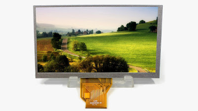
The Switch uses a 6.2" 1280x720 display. I couldn't find a monitor with the same specs, but I did find a decent looking 6.5" LCD kit. It has HDMI input and an 800x480 resolution (a curious 15:9 ratio, more on that later...) That screen is quite thick, (~6mm) but I still thought I could make it work, so started designing a case around it.
The Switch shell is pretty compact, it's only 14mm deep. (9/16") Almost half of that would be taken up by my chubby screen. So I'd have to severely slim-down the rest of the components to fit everything inside. I didn't take many photos during this process, but this is what I ended up with for the main internals...
The HDMI ports have been replaced with 0.5mm pitch FFC connectors to eliminate the bulky cables. I removed the rest of the ports, relocated the taller components and tetris'd everything so it'd fit in the case. During the build I clumisly managed to rip the delicate FFC that connects the LCD to the driver board. D'oh. Luckily the tear only severed 12 of the 50 connections. I used some very fine magnet wire to bridge the damaged area, then globbed on some epoxy to protect the joints. I also added a socket so I could extend the cable later on.
Power
I needed a way to step-up the voltage from my 3.7V battery to the 5V that the Raspberry Pi and LCD require. Initially, I picked up a cheapo eBay USB powerbank board, but couldn't find a reliable way to switch it on/off. I didn't want to physically switch the relatively high current that I'd be drawing from the battery, but because the part numbers had been ground off the ICs it was hard to find any sort of 'chip enable' signal I could tap into. So I scrapped that idea and opted for the well documented (albeit more expensive) Adafruit Powerboost 1000C. Rough tests showed I was pulling ~1200mA from 5V, this is slightly more than the 1000C was rated for...
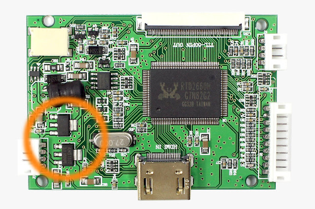
So I needed to save power. The Pi 3 was pulling ~450mA from 5V, but the display was sinking an extra 750mA! The display driver uses two linear voltage regulators for it's 3.3 and 1.8V rails. These regulators 'burn-off' excess voltage as heat, and dropping the main 5V supply down to 3.3/1.8V could be wasting a decent amount of power.
Replacing both of these chips with more efficient switching regulators would save power. But being mindful of space constraints, I only swapped out the 3.3V, and wired the input of the stock 1.8V regulator to the new 3.3V line. This saved me a fair amount of power, both in the more efficient 3.3V regulator itself, as well as doubling the efficiency of the linear 1.8V reg by having it drop a 3.3V supply instead of 5V. (3.3-1.8 = 1.5V vs 5-1.8 = 3.2V) After this change, the LCD consumed, just 400mA at 5V... much better. This reduced the total current draw of the system below 1000mA at 5V, allowing me to use the Powerboost 1000C in my portable with no problem. Now I had most of the electronics sketched out, I could turn my attention to the software and the interface...
RetroPie
I've used RetroPie before with my mini NES and SNESs, but didn't ever delve into deeply customising the layout. It was this part of the project that took the most time though, and I actually really enjoyed it. Part of the inspiration for the SwitchPi came from seeing this fantastic EmulationStation theme by lilbud.
I mentioned earlier that my screen had an unusual 800x480 resolution. This is slightly taller than the standard widescreen ratio of 16:9, potentially good news for a retro system, however the viewable area itself *is* 16:9?! It didn't make sense until I found out that the pixels weren't square like you might expect, but rectangular?! This is frustrating because there doesn't seem to be an easy way to correct for this ratio/resolution mismatch. The Official Raspberry Pi screen is similar, so I guess many people don't notice, but it really stands out to me :/
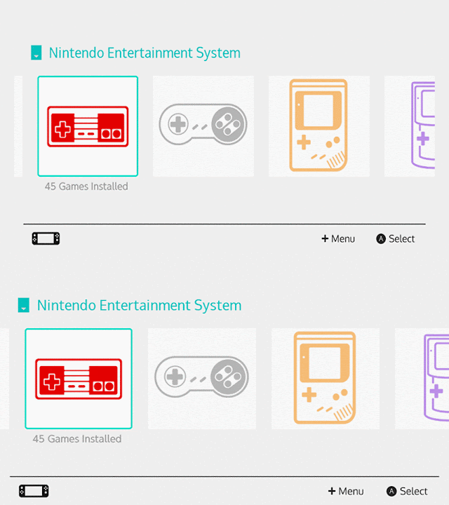 |
| If you look at the circles on the SNES controller then you might notice the distortion that needed correcting... |
I edited the font and pre-scaled all of the new assets so they wouldn't appear stretched on my oddball screen. Hats off to the guys that write RetroPie themes btw. There is tonnes of work involved. I spent ages drawing icons and tweaking layouts, and I only did a handful of systems and I started from a very good existing theme.
A fake homescreen?
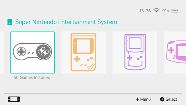
The real Switch displays the time, wifi status and battery level on it's home-screen. Unfortunately there's no option for that in EmulationStation at the moment, but it would be nice to have those features on my SwitchPi. Modifying EmulationStation to show all that information properly is a bit too involved for my understanding at the moment, but I did come up with a decent-enough hack solution... for this project at least. In an ES theme you can obviously set background images, but you can also add other images to the screen. I noticed that these images get 'refreshed' every time EmulationStation restarts after exiting an emulator. So if I made a bunch of images to represent the time, wifi, and battery, I could swap them into the theme folder when appropriate to 'update' the clock/wifi/battery icons and re-create the real Nintendo Switch home-screen. I didn't want to be constantly writing to the SD card, so I set up a small ramdisk to store the temporary files. I wrote a Python program to convert the current time into digits and copy the relevant images into the ram folder. Similarly, I wrote a script that looks at the wifi signal strength and copies over an appropriate icon. Finally, a program talks to a MAX17043 chip to grab the battery charge data and copy it into the ram folder.
All of that together gave me a working fake home screen. Except mine only updates after you exit a game. Also the Raspberry Pi doesn't have a real-time clock, so it can only pull the correct time from the network. I didn't bother adding a hardware RTC, it's not essential by any means, and I was happy with my hacky solution.
Joy-Cons
Starting off, I had problems with the Pi 3 built-in Bluetooth and had to use a separate USB dongle to pair them. I could map all the buttons with no problems but the analogue sticks only gave me a digital signal, I couldn't get a proper range of motion. Not ideal, but also not a deal-breaker for the retro games I'd be playing. Next, I needed to make the two Joy-Cons appear as a single controller. To do this, I used Linux Joystick Mapper. Making the combined map was a bit trial-and-error. It turns out the button assignments were offset, so what I thought was button '0' from 'jstest' came out as button '16' in this program. After a while though, I had this:
#Joy-Con.map by daftmike for Linux Joystick Mapper 0.4.2 [https://sourceforge.net/p/linuxjoymap] # (replace the vendor and product values to match your specific JoyCons) #Joy-Con(L) 'Portrait' Mode #------------------------------------------------------------------ button vendor=0x057e product=0x2006 src=18 target=joybtn button=0 # up button vendor=0x057e product=0x2006 src=17 target=joybtn button=1 # down button vendor=0x057e product=0x2006 src=16 target=joybtn button=2 # left button vendor=0x057e product=0x2006 src=19 target=joybtn button=3 # right button vendor=0x057e product=0x2006 src=20 target=joybtn button=4 # SL button vendor=0x057e product=0x2006 src=21 target=joybtn button=5 # SR button vendor=0x057e product=0x2006 src=24 target=joybtn button=6 # - button vendor=0x057e product=0x2006 src=29 target=joybtn button=7 # [●] button vendor=0x057e product=0x2006 src=30 target=joybtn button=8 # L1 button vendor=0x057e product=0x2006 src=31 target=joybtn button=9 # L2 button vendor=0x057e product=0x2006 src=26 target=joybtn button=10 # L3 axis vendor=0x057e product=0x2006 src=16 target=joyaxis axis=0 min=-1 max=1 deadzone=1024 # up/down stick axis vendor=0x057e product=0x2006 src=17 target=joyaxis axis=1 min=-1 max=1 deadzone=1024 # left/right stick #Joy-Con(R) 'Portrait' Mode #------------------------------------------------------------------ button vendor=0x057e product=0x2007 src=18 target=joybtn button=11 # up button vendor=0x057e product=0x2007 src=17 target=joybtn button=12 # down button vendor=0x057e product=0x2007 src=16 target=joybtn button=13 # left button vendor=0x057e product=0x2007 src=19 target=joybtn button=14 # right button vendor=0x057e product=0x2007 src=20 target=joybtn button=15 # SL button vendor=0x057e product=0x2007 src=21 target=joybtn button=16 # SR button vendor=0x057e product=0x2007 src=25 target=joybtn button=17 # + button vendor=0x057e product=0x2007 src=28 target=joybtn button=18 # [▲] button vendor=0x057e product=0x2007 src=30 target=joybtn button=19 # L1 button vendor=0x057e product=0x2007 src=31 target=joybtn button=20 # L2 button vendor=0x057e product=0x2007 src=27 target=joybtn button=21 # L3 axis vendor=0x057e product=0x2007 src=16 target=joyaxis axis=2 min=-1 max=1 deadzone=1024 # up/down stick axis vendor=0x057e product=0x2007 src=17 target=joyaxis axis=3 min=-1 max=1 deadzone=1024 # left/right stick
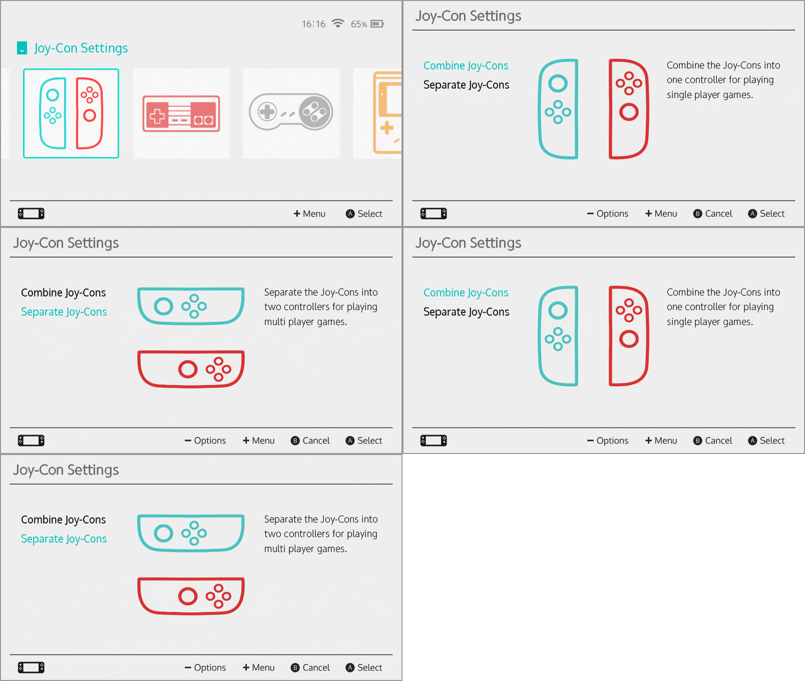
My next task was to have the Joy-Cons pair with the system at boot and automatically combine into one controller. Then afterwards, I wanted be able to combine/separate them for single and multi-player games. I'm far from an expert when it comes to writing code, but I came up with a solution with some basic Python. One problem with Linux Joystick Mapper is, if the controllers aren't found ie. before they've been connected then it will crash, so I needed a way to run it at boot, but only after both of the Joy-Cons have been paired. I came up with this script. It checks the output of 'hcitool' for the MAC addresses of my Joy-Cons. When it finds both of them, it runs joymap and copies the correct config file into the retroarch folder.
# Run at startup to combine the Joy-Cons into a single controller # (replace 'xx:xx:xx:xx:xx:xx' with the Joy-Con MAC addresses) import subprocess import os from time import sleep from shutil import copyfile def check_joycons(): joyConL = 'xx:xx:xx:xx:xx:xx' joyConR = 'xx:xx:xx:xx:xx:xx' btDevices = subprocess.check_output(['hcitool', 'con']) if joyConL in btDevices and joyConR in btDevices: return True else: return False while True: if check_joycons(): subprocess.call('sudo /home/pi/joymap/loadmap /home/pi/joymap/joycon.map &', shell=True, stdout=open(os.devnull, 'wb')) copyfile('/home/pi/joycons/combine.cfg', '/opt/retropie/configs/all/joystick-selection.cfg') copyfile('/home/pi/joycons/combine_retroarch.cfg', '/opt/retropie/configs/all/retroarch.cfg') break else: sleep(1)It's probably not the best way of doing it, but it's simple, works well and only runs once at startup. To combine/separate the Joy-Cons later on, I made a new menu item in EmulationStation with two options.
Now I can switch* between single and multi-player games and share the Joy-Cons with player two. Cool. * ; )
Other Features
On the actual Switch console, the JoyCons play a neat little 'click' sound/animation when you attach them.
You get a tactile click from the Joy-Con latch engaging with the rail, but the Switch also plays a sound effect and animation at the same time and I absolutely love it. I needed to have that on my portable too. When you attach the Joy-Cons to a real Switch, they're physically connected. On my system, they use Bluetooth, so if I wanted to trigger a 'click' sound then I'd need some way to detect when the Joy-Cons are mounted. I found some tiny limit switches in my parts bin that I pulled from an old car stereo years ago. These were just about small enough to fit in my Joy-Con rails and could be read by the Raspberry Pi to initiate the click sound. I also wanted the 'click' overlay, so I drew a sprite containing 10 frames of the Joy-Cons being attached, and used a program called spriteview to animate and display them as a transparent layer on top of the screen.
This is the left-hand side, the overlay comes down from the top of the screen and then pulls back to the edge. Combined with the sound effect, it does a convincing impression of the real thing, I was pretty happy with it. I used the same program to create an overlay for the volume controls and low-battery message too.
Kickstand
The Switch's kickstand is far from it's most lauded feature, plenty of people slated the thing, but I like it. I couldn't exactly replicate Nintendo's version in my design due to space constraints. My kickstand is shorter and non-removable, but I did make the viewing angle slightly shallower, so it's a bit more comfortable to use. It has all the same drawbacks though. You can't charge the system when using the stand, and because it's so far off centre it needs a flat surface to be stable, but it seemed like an oversight to leave it out of my SwitchPi.
Printing & Assembly
I only had enough room for the essentials in my case, this meant I had to be courageous and forego a headphone jack. But more seriously I also had no room for a fan, so my Raspberry Pi Switch would run HOT. Without any forced convection, the temperatures inside the case get too high (~50°C) for it to be printed in PLA. Instead, I used a black ABS from 3DPrima.com. It prints very nicely and held up to the high temps perfectly.
I printed the case in one piece, but because of the curves on the back I had to use some solid supports (the yellow pieces). I also went over everything with a sanding sponge to smooth some of the layer lines around the curve. I don't normally do this, but my printer struggles with curved underhangs, so it needed at least some attention. I should have done more sanding, but the little I did, went a long way and I was happy enough with the result. The last part of assembly was to make and fit a screen bezel. I picked up some Switch screen protectors, they were glass and didn't have a cut-out for the IR sensor so they'd be perfect to incorporate into my build. My plan was to mask off the visible screen area on the back of the glass and paint the outside border in black. This turned out to be trickier than I thought, it was difficult to get the mask straight and centered on all sides. After a couple of failed attempts I printed a jig to help align the masking tape. Eventually I got a result that was OK but not quite perfect. Most of it looks good, there's just one or two places where the edge is a bit rough :/
******************************************************************************************************************************************************************************************************************************
******************************************************************************************************************************************************************************************************************************
TBH I probably spent too much time writing, so my video became a bit rushed. I've made a few youtube videos before but I must have forgotten how long the editing takes :/
I also had some issues with my print that I didn't have time to correct and I mislaid a package of switches that I bought to detect the joycons (I had all the code working too) so that feature didn't make the video 
I definitely want to work some more on this project though, I very much enjoyed it and look forward to seeing everyone else's creations.



Top Comments