element14 Community
element14 Community
    Register Log In
  • Site
  • Search
  • Log In Register
  • About Us
  • Community Hub
    Community Hub
    • What's New on element14
    • Feedback and Support
    • Benefits of Membership
    • Personal Blogs
    • Members Area
    • Achievement Levels
  • Learn
    Learn
    • Ask an Expert
    • eBooks
    • element14 presents
    • Learning Center
    • Tech Spotlight
    • STEM Academy
    • Webinars, Training and Events
    • Learning Groups
  • Technologies
    Technologies
    • 3D Printing
    • FPGA
    • Industrial Automation
    • Internet of Things
    • Power & Energy
    • Sensors
    • Technology Groups
  • Challenges & Projects
    Challenges & Projects
    • Design Challenges
    • element14 presents Projects
    • Project14
    • Arduino Projects
    • Raspberry Pi Projects
    • Project Groups
  • Products
    Products
    • Arduino
    • Avnet Boards Community
    • Dev Tools
    • Manufacturers
    • Multicomp Pro
    • Product Groups
    • Raspberry Pi
    • RoadTests & Reviews
  • Store
    Store
    • Visit Your Store
    • Choose another store...
      • Europe
      •  Austria (German)
      •  Belgium (Dutch, French)
      •  Bulgaria (Bulgarian)
      •  Czech Republic (Czech)
      •  Denmark (Danish)
      •  Estonia (Estonian)
      •  Finland (Finnish)
      •  France (French)
      •  Germany (German)
      •  Hungary (Hungarian)
      •  Ireland
      •  Israel
      •  Italy (Italian)
      •  Latvia (Latvian)
      •  
      •  Lithuania (Lithuanian)
      •  Netherlands (Dutch)
      •  Norway (Norwegian)
      •  Poland (Polish)
      •  Portugal (Portuguese)
      •  Romania (Romanian)
      •  Russia (Russian)
      •  Slovakia (Slovak)
      •  Slovenia (Slovenian)
      •  Spain (Spanish)
      •  Sweden (Swedish)
      •  Switzerland(German, French)
      •  Turkey (Turkish)
      •  United Kingdom
      • Asia Pacific
      •  Australia
      •  China
      •  Hong Kong
      •  India
      •  Korea (Korean)
      •  Malaysia
      •  New Zealand
      •  Philippines
      •  Singapore
      •  Taiwan
      •  Thailand (Thai)
      • Americas
      •  Brazil (Portuguese)
      •  Canada
      •  Mexico (Spanish)
      •  United States
      Can't find the country/region you're looking for? Visit our export site or find a local distributor.
  • Translate
  • Profile
  • Settings
Geeky Gadgets
  • Challenges & Projects
  • Project14
  • Geeky Gadgets
  • More
  • Cancel
Geeky Gadgets
Blog Build your own Torch/Flashlight!
  • Blog
  • Forum
  • Documents
  • Events
  • Polls
  • Files
  • Members
  • Mentions
  • Sub-Groups
  • Tags
  • More
  • Cancel
  • New
Join Geeky Gadgets to participate - click to join for free!
  • Share
  • More
  • Cancel
Group Actions
  • Group RSS
  • More
  • Cancel
Engagement
  • Author Author: shabaz
  • Date Created: 14 Jun 2017 4:43 AM Date Created
  • Views 9056 views
  • Likes 12 likes
  • Comments 12 comments
  • xp-e
  • led lighting
  • torch
  • cree
  • flashlight
  • ggadgetsch
Related
Recommended

Build your own Torch/Flashlight!

shabaz
shabaz
14 Jun 2017

Introduction

It's fairly geeky to want to make your own flashlight!

This project offers over 260 lumens of light output (approaching some typical LED lights for home use) and is powered by three AA or AAA batteries, or a single lithium ion (Li-ion) cell.

It was built from scratch in about 4 hours, using whatever I had handy.

Here it is not shown, because the light is very bright! I held a 5mm thick sheet of perspex in front of it.

image


The Circuit for Flashlight 'A'

The circuit is shown here. Basically it just consists of a DC-DC converter using a Texas Instruments LM2733X chip. The LEDs are Cree XP-E, and are quite bright!

There are two LEDs, for double the power : ) For ease of reference this circuit will be called Flashlight 'A':

image

The parts included:

LM2733X DC-DC converter ICLM2733X DC-DC converter IC

MBR0520LMBR0520L

15uH inductor15uH inductor

2.2uF capacitor 08052.2uF capacitor 0805

10uF 16V capacitor 080510uF 16V capacitor 0805

330pF capacitor 0603330pF capacitor 0603

68k resistor 060368k resistor 0603

12k resistor 060312k resistor 0603

47k resistor 060347k resistor 0603

Cree XP-E Cool White LEDsCree XP-E Cool White LEDs (two required)

LED reflectorLED reflector (two required)

3xAA battery holder3xAA battery holder

Slide switch panel mountSlide switch panel mount

Possible suitable casePossible suitable case

Bergquist 804090 MCPCB or similar (XP-E MCPCB often on ebay)

PCB or protoboard as required


Building It

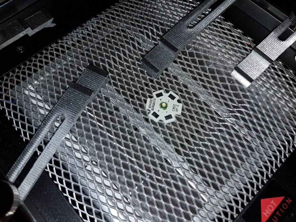
For the LEDs, I had some metal core PCBs (MCPCB) made by Bergquist. I've had them for about a year or two and done nothing with them. I put some solder paste on them and then put the LED on top, and put it on top of a heat source. The heat source that I used was a pre-heater, but people have been known to use all sorts of cooking methods (note: solder and flux is toxic, don't use stuff that you use for cooking food!).

image

Next, I built up the rest of the circuit using a SMD prototyping board and normal hand soldering methods. It would be nice to build this on a custom PCB eventually.

image

Testing It

I have not done much testing, I just checked current consumption for now. The current drain from three AA batteries is about 1.05A, so they should last a couple of hours. The current through the LEDs is approximately 450mA. The datasheet states that the output is 107 lumens minimum at 350mA, and at 450mA it is expected to be about 125% of this value according to the charts. So, this means more than 260 lumens should be output for the two LEDs, but it will also depend on the LED temperature. With the metal core PCB it should be very easy to bolt on a heat sink if needed to keep them cool. For use as a flashlight it could also be good to have some dual reflectors for focusing to a tighter beam.


Summary

This short project resulted in a reasonably powerful flashlight. It is fairly easy to build! The difficulty will be enclosing it in a nice handheld package. I think it is worth the effort for all geeks : )


Flashlight 'B'

The next iteration of the design, called Flashlight B, uses a TI LM3410XLM3410X part, and dual Cree XM-L2 LEDs. It is discussed in the comments below. Here is the schematic:

image

A PCB was drawn up for this (the gerber files that can be sent to any PCB manufacturer are attached to this blog post, just before the comments section. The filename is export-flashlight-b-rev1.zip) :

image

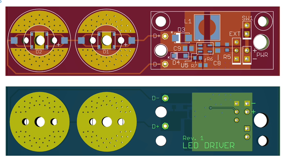
The PCB is composed of the driver, and two circular areas where the LEDs will go. The PCB can be used in a single piece, or alternatively the PCB could be cut if it is desired to locate the circular LED areas somewhere else in an enclosure.

The boards arrived:

image


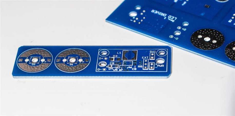
They have not been assembled or tested yet.. bookmark to watch this space!

Attachments:
export-flashlight-b-rev1.zip
  • Sign in to reply

Top Comments

  • shabaz
    shabaz over 8 years ago +4
    I made some progress with a dual XM-L2 design, I'm hoping this one is around 600 lumen ballpark, with just slightly more current consumption (perhaps 1.1A at 4.5V). This uses the TI LM3410X driver chip…
  • jw0752
    jw0752 over 8 years ago +3
    Hi Shabaz, Nice project. Since we have DC to DC converters that approach 100% efficiency you would think we could come up with a more efficient electricity to light conversion so we could get away from…
  • shabaz
    shabaz over 8 years ago in reply to jc2048 +3
    Hi Jon! As you say, the efficiency isn't great, I just used what I had. I do want to build something with a couple of the more powerful (and more efficient) XM-L2 LEDs, and with LM3410X I think it could…
  • shabaz
    shabaz over 7 years ago

    Added documentation concerning the next iteration, called Flashlight 'B' to the main body of the blog post.

    image

    • Cancel
    • Vote Up 0 Vote Down
    • Sign in to reply
    • More
    • Cancel
  • shabaz
    shabaz over 8 years ago

    I made some progress with a dual XM-L2 design, I'm hoping this one is around 600 lumen ballpark, with just slightly more current consumption (perhaps 1.1A at 4.5V). This uses the TI LM3410X driver chip. There is also an 'Ext' port on the PCB for connecting up an Arduino or whatever in future, for providing dimming.

    image

    For the LEDs, I've made a 3mm hole for soldering a copper rod, if it works then this is a super-cheap (and easy) way of getting the heat out.

    image

    The rear is just copper, for a bit more cooling. The two side holes are for attaching the reflector (the same part number as mentioned before), it isn't designed for this LED, but it looks like the XM-L2 dies are at identical height to XP-E, and the angle for illumination spread is near-identical too. To make the reflector fit, the hole at the rear of it will need to be drilled to 5mm.

    image


    image

    • Cancel
    • Vote Up +4 Vote Down
    • Sign in to reply
    • More
    • Cancel
  • shabaz
    shabaz over 8 years ago in reply to jc2048

    Hi Jon!


    As you say, the efficiency isn't great, I just used what I had. I do want to build something with a couple of the more powerful (and more efficient) XM-L2 LEDs, and with LM3410X I think it could approach 600 lumens (i.e. more than twice the light output) for only slightly higher current consumption, so it should still function on 3xAA batteries.  I only ran a brief simulation but it seemed feasible. I might draw up a PCB for that, perhaps in snappable sections, the LED part using the copper rod method mentioned earlier (below), to keep it low-cost and avoiding metal-core boards.

    • Cancel
    • Vote Up +3 Vote Down
    • Sign in to reply
    • More
    • Cancel
  • shabaz
    shabaz over 8 years ago in reply to jc2048

    Hi Jon,


    That's a good idea! Also, now I think of it, there was a useful part which was available but is no longer in production : ( it was a copper peg intended for insertion into a board, to pull out heat onto a heat sink behind the board. The XM-L2 is just about large enough to do something similar with a 3mm diameter copper rod, i.e. solder one end of the (very short) rod onto the centre of the LED (which is isolated from the anode/cathode) and poke the other end into a 3mm hole in a heat sink (with thermal epoxy in it). This would work with any (e.g. fiberglass) copper clad board in-between with 3mm hole.

    • Cancel
    • Vote Up +1 Vote Down
    • Sign in to reply
    • More
    • Cancel
  • jc2048
    jc2048 over 8 years ago in reply to jw0752

    Whilst convertors can be efficient, this particular circuit isn't (doesn't matter at all - it's a quickly thrown together Geeky Gadget, not a carefully considered production design). From Shabaz' figures


    input power: 4.5V x 1.05A = 4.725W


    power to LEDs: 6.2V x 0.45A = 2.79W


    efficiency = 2.79/4.725 x 100% = 60%


    Some of that is possibly down to the fact that it looks like it isn't regulating directly but is operating on the internal switch current limit.


    But you're right - that's still better than the conversion from electrical power to light.

    • Cancel
    • Vote Up +2 Vote Down
    • Sign in to reply
    • More
    • Cancel
>
element14 Community

element14 is the first online community specifically for engineers. Connect with your peers and get expert answers to your questions.

  • Members
  • Learn
  • Technologies
  • Challenges & Projects
  • Products
  • Store
  • About Us
  • Feedback & Support
  • FAQs
  • Terms of Use
  • Privacy Policy
  • Legal and Copyright Notices
  • Sitemap
  • Cookies

An Avnet Company © 2025 Premier Farnell Limited. All Rights Reserved.

Premier Farnell Ltd, registered in England and Wales (no 00876412), registered office: Farnell House, Forge Lane, Leeds LS12 2NE.

ICP 备案号 10220084.

Follow element14

  • X
  • Facebook
  • linkedin
  • YouTube