

 Connectors Series - Part 1 - Basics
A connector system performs the all important role of interconnecting a product’s printed circuit boards (PCBs), power supplies, control panels and other sub-assemblies. While connectors may appear to play a passive role in an end-product’s performance, in reality, they influence the safety, reliability, and ease-of-maintenance of a product. To select the ideal type of connector for a specific design or application, a design engineer can benefit from a basic knowledge of connector technology.
Related Components | Test Your Knowledge 
sponsored by 
Vote for the next Learning Module subject!
2. Objectives
The objective of this learning module is to provide you with the essentials of connector technology. You will first learn the purpose, function, and components of a connector. In the later sections, you will gain a deeper understanding of the types, materials, features, and applications of PCB, Card/Slot and I/O connectors.
Upon completion of this module, you will be able to:
- Define what connectors are and the purpose they serve;
- Discuss the primary functions of a connector;
- Describe the anatomy of a connector;
- Identify the most common types of connectors.
3. Definition

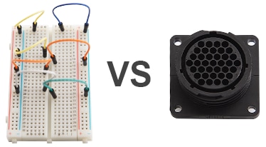
What is a connector? Is a connector simply a means to connect two electrical points of a circuit, or is its purpose broader in scope? To understand the purpose of a connector, let us consider a jumper wire. Is a typical jumper wire – one that connects circuit components together on a prototyping breadboard – a connector?
A jumper wire can connect two points of a circuit together, but lacks the mechanical integrity or environmental protection required in an end-product that is subjected to vibrations, abuse, corrosion or water sprays. In this respect, a connector provides more than a means of electrical connection, but should offer a durable mechanical or mating connection as well. So, maybe a jumper wire falls short as a connector.
If a jumper wire isn’t a connector, then what exactly is? Let’s look at the definition of connector to find out:
A connector is a device that is capable of connecting two circuit points, signals, or sub-systems with electrical integrity, mechanical durability, environmental protection and safety.
- Electrical Integrity - when connectors mate two points of a circuit with a very low contact resistance and provide protection from electromagnetic interference (EMI) and/or electrostatic discharge (ESD).
- Mechanical Durability - when a connector can withstand vibrations or environmental abuse without causing a failure in electrical integrity.
- Environmental Protection - when a connector’s design meets the IP (Ingress Protection) ratings defined in the international standard EN/IEC 60529 for preventing the ingress of water, dust, debris, and other contaminants that would otherwise interfere with the electrical integrity of the connection.
- Safety - when a connector is designed with features that eliminate personnel hazards, or the risk of fire, shock or electrocution.
4. Function
To understand the function of a connector, let’s imagine for a moment a world without connectors. What would be the practical outcome of such a scenario?
In such a world, all electronic components, sub-assemblies and electrical power would be connected by bare metal wiring. This means everything would be soldered, mechanically attached or twisted together. Doesn’t sound convenient, does it?
It would be pretty hard to design products with high-circuit densities in a “No Connectors Allowed” world. Smart phones would probably be a lot bigger. And forget about portable charging stations or even your handy power adapter!
What about electrical safety? Would a ”No Connectors Allowed” world be safer for a user? Could you safely connect the 120/230V mains to your home appliance without sparks flying? (Probably not!) It’s time to go back to a world with connectors and learn the primary functions of a connector.
The primary functions of a connector are:
- Quick Connection/Disconnection: Connectors provide a safe, quick and convenient means for connecting and disconnecting components, modules, systems and sub-assemblies during prototyping, manufacturing, installation, operation, or maintenance.
- Efficient Manufacturing: Connectors allow for the efficient production of products by eliminating many time-consuming tasks such as soldering.
- Easy Upgrades/Configurations: Connectors enable users to easily upgrade products or quickly configure new devices for these products.
- Eliminate Safety Hazards: Connectors shield users from hazardous currents that could pose a shock or electrocution hazard.
5. The Anatomy of a Connector
There are many types and styles of connectors, yet they all share common characteristics. In this section, we will discuss the common components and features of a connector.
The three main parts of a connector are:
- Housing
- Shell
- Contact
- 5.1 Description of a Housing
The housing is the component that provides a connector the mechanical durability, environmental protection and electrical insulation for the contact terminals.
Connector housings have the following characteristics:
- Materials: Housings are made of stabilized, heat resistant, self-extinguishing thermoplastic material.
- Locking: Housings often have a locking tab to prevent connector housing halves from disconnecting and interrupting a circuit.
- Polarization: Housings are polarized to ensure the connector halves are mated correctly.
- Keying: Housings are keyed or arranged so only compatible contacts or circuits can be mated with one another.
- Environmental Protection: Housing often have shrouds or seals (depending upon the specifications of a connector) to prevent the ingress of dust, moisture, chemicals and other contaminants that could degrade the electrical integrity of the connection.
- Mounting: Housings can be mounted in a variety of ways, including PCB, panel, and wire-to-wire configurations.
- Fire Safety: High-performance composite materials help meet the low smoke, toxicity and flammability (UL 94V-0 rated) requirements of the application.
- 5.2 Description of a Shell

The shell encloses the connector housing thereby offers added strength and protection to the housing. Since shells are made of a nickel-plated, zinc alloy, they also offer excellent corrosion resistance.
- 5.3 Description of Contacts and Terminals


The contact consists of highly conductive material with very low resistance that allows the easy flow of electrical current through the two mated contacts.
While the contact is the point where circuit current flows, the terminal is the means by which the contact is attached (or terminated) to a circuit’s conductor. Often times the functions of both the contact and terminal are combined in one device. In this case, the word terminal and contact maybe used interchangeably.
Contact terminals have the following characteristics:
- Materials: A variety of materials or alloys are used for electrical contacts and terminals based upon cost, electrical and thermal properties, resistance to oxidation (corrosion) and durability. The most common contact metals include: brass, phosphor bronze, and high copper alloy. Contacts are often plated for added strength, better conductivity and corrosion resistance. Plating materials include gold, silver nickel, tin, and palladium-nickel.
- Types: Contacts are constructed in the form of insertable/removable pins and sockets (informally referred to as “male” and “female,” respectively).
- Locking: Terminals often have locking wing tabs to securely hold the terminal in the connector’s housing.
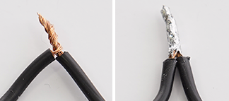
- 5.4 Description of Terminations
Terminations are the manner by which the circuit’s conductors are attached to the connector’s contact terminals. The quality of the terminations is critical to the proper functioning of the circuits connected by a connector.
Electrically sound terminations maintain a desirable low contact resistance at the point of connection. Conversely, terminations that are not electrically sound —opened, shorted, or high resistance points —can be detrimental to the proper functioning of the circuit. This is a particular concern in high vibration environments (industrial machinery or automotive applications).
The common types of terminations include:


6. Types of Connectors
There are a wide variety of connector-types used by design engineers and employed in prototypes and end-products. In general, connectors are grouped into the following main categories:
- PCB
- Card/Socket
- Input/Output
- 6.1 PCB Connectors
 TE Connectivity 1744057-5 wire-to-board connector, Economy Power |
Wire to Board a type of connector that offers a separable connection between electronic sub-assemblies, PCBs, and rack/panels. Benefits include saving PCB space, enabling high-density connections, and providing design flexibility. |
 TE Connectivity 3-2041390-9 ZIF Flexible Printed Circuit Connector |
Zero Insertion Force (ZIF) a type of wire-to-board connector that minimizes the insertion or extraction force, reducing contact wear. It is used with flat flex ribbon cable and has a mechanical arm that locks the contacts in place upon connection. |
 TE Connectivity Board to Board Connector, Fine Pitch |
Board to Board a type of connector that connects one PCB to another in a stacking configuration. These connectors are for low-profile, tight-packaging or backplane connector applications. |
 TE Connectivity Ribbon Cable Connectors |
Ribbon a type of connector used with flat ribbon cable to connect internal peripherals in computers, such as hard drives, CD drives and floppy drives. The ribbon connector is typically attached to the cable via insulation displacement rather than crimping or soldering, which allows for the mass termination of contacts. |
- 6.2 Card/Socket Connectors
 TE Connectivity AMP Card Edge Connector Receptacle1761465-3 |
Card Edge a multi-circuit receptacle (female) that mates with the header (male) that's formed out of the traces that run to the edge of a PCB. They are primarily used in personal computers for connecting expansion cards, cartridges and computer memory to the system bus. |
 TE Connectivity’s AMP IC & Component Socket, 800 Series, DIP |
Package to Board (IC Socket) a connector that provides a separable connection between an IC chip and a PCB via a through-hole soldered socket. |
 TE Connectivity 1939870-1 SD Card Connector EMBOSS ASSY |
Memory Card a type of connector that connects microSD, SD, SIM, and/or MMC memory cards to portable or remote devices. They offer a variety of ejector types (e.g., push-push and push-pull) and provide polarization features to prevent improper card insertion. |
||
- 6.3 Input/Output Connectors
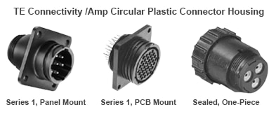
 TE Connectivity’s AMP Circular Plastic Connector Housing, Series 1, Panel Mount and Metal-Shell Circular Plastic Connector Housing, Panel Mount208473-1 |
Circular Plastic/Circular Metal a type of customizable, sealed or unsealed, commercial connector designed for power and signal connections and used in industrial, automotive, signal processing, power management and computer applications. Both CPC and CMC connectors are made of stabilized, heat resistant, self-extinguishing thermoplastic material. CMC connectors have an additional metal shell to add greater strength and durability. |
 TE Connectivity’s AMP DIN Audio Video Connector PCB Mount5749230-1 |
S-Video an audio/visual connector used for transmitting Super-Video (S-Video) signals. The connector separates luminance and chrominance for a better picture and also to eliminate dot crawl. |
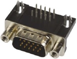 TE Connectivity’s AMP Standard D Sub Connector Amplimite HD-22 Series DE-155749768-1 |
Video Graphics Array (VGA) an analog, audio/visual connector for connecting PC displays. In graphics mode, the resolution is either 640 by 480 (with 16 colors) or 320 by 200 (with 256 colors). The original VGA standard has evolved over time to provide better resolution and more colors (e.g., SVGA and XGA). |
 TE Connectivity 1734148-1 DVI Digital Video Interface Connector, Integrated Analog & Digital (DVI-I), PCB Mount |
Digital Visual Interface (DVI) a digital video connector used as an interface between computers, LCD monitors, projectors and other digital display equipment. It's based on the standard created by the Digital Display Working Group (DDWG) for converting analog signals into digital signals. It uses differential pairs for higher quality and better resolutions than VGA. It has RGB pins for backwards compatibility. It comes in a variety flavors, including DVI-D single link, DVI-D dual link, DVI-I single link, DVI-I dual link and DVI-A, analog. |
 TE Connectivity HDMI Connector Type A PCB Mount1746679-1 |
High-Definition Multimedia Interface (HDMI) an uncompressed, all-digital, audio/video interface/connector between any audio/video source, such as a set-top box, DVD player or A/V receiver, and an audio/video monitor such as a digital television (DTV). Unlike DVI, HDMI is both an audio and visual interface. HDMI has the capacity to support existing high-definition video formats such as 720p, 1080i, and 1080p, among others. |
 TE Connectivity’s AMP DisplayPort Digital Audio Connector Receptacle PCB Mount2040210-1 |
Display Port a digital display connector that employs packetized data transmission to connect a video source to an high definition (HD) video display. Developed by the Video Electronics Standards Association (VESA), it's an evolution of HDMI that supports higher resolutions as well as daisy-chaining. DisplayPort is backward compatible with VGA and DVI through the use of adapters. |
 TE Connectivity’s AMP Standard D Sub Connector AMPLIMITE HD-20 Series DE Receptacle 93-1634222-2 |
D-subminiature (D-sub) a peripheral connector commonly used for connecting RS-232 serial communication devices It contains a D-shaped metal shield that provides mechanical support ensures correct orientation and offers some level of EMI protection It is easy to work with and solder and its pin numbers are labeled on the connector But it is not as popular as in the past It also takes up a lot of space and has limited mounting options |
||
|
USB a connector based on the Universal Serial Bus specification, developed by the USB Implementers Forum, to standardize the connection of computer peripherals to personal computers, for both communicating and supplying electric power. The current types include: |
|||
 TE Connectivity 2129691-1 USB, 3.1 TYPE C |
USB Type-C
the new standard plug or receptacle providing a multi-function, reversible, single cable solution for USB, power, and audio/video. |
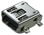
 TE Connectivity’s AMP 1981568-1 MICRO USB 2.0 TYPE B, RCPT, SMT |
Micro USB 2.0
mostly used in mobile devices and is the smallest connector series in the USB family. |
 TE Connectivity USB 3.0 TYPE A RECEPTACLE SMTT1932258-1 |
USB 3.0
support a 5Gbps data rate for fast syncing on the go—a 10x performance increase over USB 2.0. |
||
|
Coaxial an I/O connector that’s designed to work at radio frequencies in the multi-megahertz range. RF Products Overview (click on image to enlarge)  All products are RoHS compliant Based on product type, design and manufacture to comply with standards: MiL-C-39012, Mil-STD-348, CECC, IEC for features and applications visit TE.com |
|||
|
Modular Jack used to connect telephone systems or Ethernet networks. Common examples are RJ11 (telephone) and RJ45 (Ethernet) jacks. |
|||
 TE Connectivity’s AMP CONN RJ45 CAT62170668-1 |
|||
*Trademark. TE Connectivity, andTE Connectivity Corporation are trademarks of TE Connectivity Ltd. Other logos, product and/or company names may be trademarks of their respective owners.
Test Your Knowledge
Connector Skills 1

Are you ready to demonstrate your Connectors knowledge? Then take a quick 15-question multiple choice quiz to see how much you've learned from this Essentials Connectors 1 module.
You'll see your score at the end of the quiz. If you score 100%, you're on your way to earning your Connectors Skills 1 badge, and 100 points. To fulfil all the requirements for earning the badge, you will also need to post a feedback comment on this Essentials Connectors 1 page to let us know what you thought of the module, and bookmark this page so you’re the first to hear when Module 2 is published.
Top Comments
-

balearicdynamics
-
Cancel
-
Vote Up
+1
Vote Down
-
-
Sign in to reply
-
More
-
Cancel
-

COMPACT
in reply to balearicdynamics
-
Cancel
-
Vote Up
+3
Vote Down
-
-
Sign in to reply
-
More
-
Cancel
-

balearicdynamics
in reply to COMPACT
-
Cancel
-
Vote Up
0
Vote Down
-
-
Sign in to reply
-
More
-
Cancel
-

COMPACT
in reply to balearicdynamics
-
Cancel
-
Vote Up
+1
Vote Down
-
-
Sign in to reply
-
More
-
Cancel
Comment-

COMPACT
in reply to balearicdynamics
-
Cancel
-
Vote Up
+1
Vote Down
-
-
Sign in to reply
-
More
-
Cancel
Children