 MCUs Series - Part 3 - Industrial Applications
Microcontrollers are embedded in a range to consumer and commercial products, as well as a wide variety of industrial applications. Since many industrial applications employ automated systems, these applications can benefit from the use of microcontrollers.
Related Components | Test Your Knowledge 
The usual benefits of a smaller footprint, lower heat dissipation, flexible design and programmability accrue from the use of microcontrollers. However, industrial applications and their inherent environments are sufficiently different from home or consumer uses to merit a discussion of industrial microcontrollers as a separate learning module.
Low-power microcontrollers and wireless microcontrollers have been discussed in earlier Essentials Modules. MCUs for industrial applications are going to be discussed in this module.
2. Objectives
The objective of this learning module is to provide you with an overview of Microcontroller Units (MCUs) as used in industrial environments.
Upon completion of this module, you will be able to:
- Understand the industrial usage environment
- Identify the most common industrial applications
- Understand how MCU devices cater to industrial applications
- Learn about some currently available Industrial MCU devices
3. Common Industrial Applications
Three things need to be considered when specifying MCUs for industrial applications:
- How is the industrial operating environment different from consumer environments?
- Does the industrial environment call for different kinds of MCU devices?
- Are the use cases/applications sufficiently different to affect the features required of Industrial MCU devices?
Most MCU manufacturers offer a range of products that are suitable for industrial/harsh environments. In both this section and the next, we will explore these industrial environments and the devices suitable for such usage conditions.
The most common industrial applications should tell us the features one should look for in devices being offered by manufacturers. In addition, developers need the best tools to make the development process as simple as possible. What would also be welcomed are tools, ready-made components, and application support that can help compress the time-to-market.
Industrial applications fall into the following general categories: (Note: This is by no means an exhaustive list; it just lists some of the frequently used types.)
- Motor Drive & Control
- Industrial Drive Control
- Servo Drive Control
- Elevator Control in Buildings
- Automation & Process Control
- Data Collection, Monitoring via Industrial Sensors
- Monitoring & Human Machine Interface (HMI)
- Simple Graphics-Based MIMIC Displays
- Full Multi-Media Capable Displays
- High-End Digital Power
- Lighting and Environmental Control
- Industrial Safety Applications
Typically, industrial control, monitoring and other associated equipment are arranged across a factory floor or operational area. Each of these individual systems will have a connection to a central display panel and the operators' console (the HMI) to help operators monitor what's happening at various locations so he/she can make necessary adjustments to the control applications on the floor.
4. The Industrial Environment
The first thing to note is that electronic devices in the industrial environment need to be capable of operating in harsher environments than is typical of commercial/home situations. The biggest issue is the operating temperature. For the semiconductor devices in the MCU, the junction temperature is the most important consideration for assuring dependable operation. As the junction temperature increases, the device performance deteriorates. Leakage currents increase with increasing junction temperature, which raises the chip substrate temperature. Higher temperatures also affect the physical characteristics of the semiconductor device.
Higher chip temperatures can also affect the metallic interconnections between devices "on chip" and the I/O pins used for communication with the external world. In general, higher temperatures can cause catastrophic damage of the device. In response, manufacturers typically specify a temperature range within which published characteristics of the devices hold true.
The junction temperature Tjunction that a device reaches is related to the ambient temperature Tambient and the amount of steady state power dissipation within the device. A commonly used relationship is as follows:
Tjunction = Tambient + P * θ
Where "P" is the power dissipated in watts, theta (ө) is the thermal resistance from junction to the ambient. Theta is expressed as degrees Celsius per watt.
A heat sink may be needed to connect the heat flow from the case to the ambient and the temperature rise must be calculated using both the junction-to-case and case-to-ambient thermal resistance values. Since the construction of the devices (specifically, package type) offers different resistances, the choice of a package type will be an important factor when choosing a device for an application.
The operating temperature range for consumer/home equipment is generally considered to be 0 to 70 degrees Celsius. Industry-grade temperatures range from -40 to 85 degrees Celsius, but there are no fixed ranges. Some manufacturers may supply devices with slightly different temperature ranges. The essential point here is that manufacturers must test finished devices and categorize them for each use.
Besides low and high operating temperatures, high humidity and mechanical vibrations need to be considered for the industrial environment. Only hermetically sealed packages can prevent any ingress of moisture into the package. If moisture ingress were to occur, it would damage the piece of silicon inside. Other package types with leakage tend to breathe in moisture and retain it inside the package. Vibration, electromagnetic interference (EMI) and electrostatic discharges (ESD) are other factors to be considered when putting together a system and designing its packaging within an enclosure.
In addition, an industrial environment with heavy motors and other rotating equipment contribute to the RF noise interference and the overall noise to a large degree. RF interference is a given as is the ESD in this interconnected world of wired networks. A static discharge at a distant point can have an immense effect on the local system.
Often, the subsystems of an industrial control system are distributed all over the factory floor. For the purposes of monitoring and controlling of these dispersed subsystems, a human machine interface (HMI) is utilized. Since running multiple wires to facilitate parallel communication can create quite a tangle, serial communication is thus the preferred mode of communication. Moreover, there are a couple of issues related to communication and control. For instance, communication voltage levels are at + and – 24v levels, so that communication is possible even in a noisy industrial environment. The electronics, on the other hand, operate at 5v or less (3.3/ 2.5 v, etc.). Control signals follow the 20mA loop standard. Necessary "glue" components, when available from the same manufacturer, are very helpful. The preferred suppliers will be those manufacturers who have ancillary components to mitigate the effects of these factors. Additional factors one may encounter in the industrial environment include toxic fumes, contaminants in the surrounding air, dust and grease, and potentially explosive atmospheres, etc.
5. MCU Devices for the Industrial Environment
When you start getting into your actual design work, the choice of devices is the most important task. Obtaining the most performance for the least cost is the primary goal of the designer. In this quest for an appropriate device, designers must ensure that the device they select will work at the temperature range and other harsh environmental conditions of industrial applications. Manufacturers help in this respect by clearly identifying their devices as "industrial grade." Device selection then must be guided by the required features.
No matter what's the application for which you are designing, there are some requirements that can be identified as essential for devices to be used in industrial grade applications. So, let's go over the kinds of applications in the industrial environment that we discussed earlier, and see if there are some common features that can be discovered.
Common features of any precision and high-resolution closed loop control system typically include, frequent sampling of parameters being monitored, the processing of these inputs, and the frequent correction outputs. Floating point values/variables being handled at fast intervals require quite a bit of "horsepower" on the part of the MCUs in use. Most manufacturers thus have high-performance, MCU devices for the industrial space. TI groups these devices as "performance" devices. In addition to industrial uses, the performance group is also utilized in automotive and other power applications.
A robust I/O structure that lets you connect to analog/digital sensors is another common feature. ADCs used in these applications often are high resolution (12-bit or more) and have fast sampling and digitizing operations. Digital sensing peripherals are expected to read inputs at a fast rate. Another requirement that must be well supported is communication capabilities. Serial communication support, as well as network connectivity, is often required. The network connectivity is often a serial bus-based, Ethernet-like system. In automotive situations, Control Area Networking (CAN) pre-dominates.
Since the TI product lines are extensive, they are a good way to illustrate the kind of devices that let designers/developers implement industrial applications easily.

Real-Time Control MCUs are used in high-performance, closed loop control applications. These may be in used in the power electronics space or many other feedback applications. The Control + Automation group of MCUs are used in closed loop control applications. These devices support connectivity and system automation. Safety MCUs are primarily for situations where failsafe designs are of prime importance; they help users create systems that comply with the functional safety standards such as the IEC 61508 and ISO 26262 standards. These also help provide performance for safety critical applications. The following sections discuss these device families.
- 5.1 Real-Time Control MCUs
As 32-bit microcontrollers, the C2000 microcontroller devices family is optimized for processing, sensing, and actuation to improve closed loop performance. They consist of:
- C2000 Delfino MCUs
- C2000 Piccolo MCUs
- C2000 InstaSPIN MCUs
- C2000 F28x MCUs
C2000 MCU units are positioned for real-time applications that include motor control, solar, and renewable energy as well as digital power supplies; smart grid applications, radar, LED lighting applications and anything else that needs complex signal processing. The capability to process digital signals conveniently comes from the fact that this MCU has been built around TI's 32-bit DSP core. Other performance boosting features include a single cycle multiply operation in 32x32 bit numbers and instructions that execute in a single cycle.
The InstaSPIN MCUs are C2000 controllers with customized motor control libraries loaded into their ROMs. These are discussed in a separate section (5.2).
Delfino microcontroller products consist of the following:
- TMS320F2837xD
- TMS320F2837XS
- TMS320C2834x
- TMS320F2833x
The individual devices in each series differ in memory size and configuration.
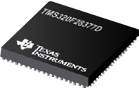
TMS320F2837xD Dual-Core Delfino Microcontrollers
Let's take a closer look at the top of the line device, the TMS320F2837xD. The MCU is a dual core 800 MIPS processor. But you can have more performance than what this 800 MIPS indicates. The MCU has two Control Law Accelerators (CLA). The CLAs are independent co-processors built into the device and can execute the complex control logic you use for a control loop. That frees up the main processor for additional computation. 1 MB Flash and 204 KB of SRAM are available. Other devices in the family have lower memory resources than this. 24 High resolution pulse width modulator (HRPWM) output channels are also available. It has four ADCs that have 16-bit/12-bit capability, high speed 1.1 Mega samples per second (MSPS), and 3.5 MSPS in 12-bit configuration capabilities.
Other devices provide lower performance and comparatively lower memory and peripheral capabilities. For example, the TMS320F2833x processor provides only about 100 to 150 MIPS; though it is quite high performance compared to many other MCUs.
Piccolo devices are directed at closed loop control applications in general. The Piccolo line has six sets of products available. These are designated as:
- TMS320F2807x Piccolo MCUs
- TMS320F2806x Piccolo MCUs
- TMS320F2805x Piccolo MCUs
- TMS320F2804x Piccolo MCUs
- TMS320F2803x Piccolo MCUs
- TMS320F2802x Piccolo MCUs
TMS320F2807x Piccolo Microcontrollers
Like the Delfino series, the individual members in the Piccolo series vary in memory configuration but have the same CPU and other peripherals. CPU performance changes across the series. The 2807x series is the highest rated. Except for the 2802x series, the CPUs have a coprocessor. Performance for the top 2807x is 100 to 240 MIPS. Memory configuration includes an ECC check on the entire memory area. Piccolo MCU configurations are indicated in the following table.
| 2807x | 2804x | 2806x | 2805x | 2803x | 2802x | |
|---|---|---|---|---|---|---|
| MIPS | 100-240 | 100-200 | 90-180 | 60-120 | 60-120 | Up to 60 |
| Flash | 512 KB | 256 KB | 256 KB | 128 KB | 128 KB | 64 KB |
| RAM | 100 KB | 100 KB | 100 KB | 20 KB | 20 KB | 12 KB |
| PWM | 24 Channel, HRPWM | Up to 16 Channels, HRPWM | 14 channels, HRPWM | 14 channels | 14 channels, HRPWM | 8 channels, HRPWM |
| ADC | 12-bit, 3x S/H, 3.1 MSPS | 12-bit, 3x S/H, 3.1 MSPS | 12-bit, 2x S/H, 3.46 MSPS | 12-bit, 2x S/H, 3.75 MSPS | 12-bit, 2x S/H, 4.6 MSPS | 12-bit, 2x S/H, 4.6 MSPS |
Definitions: high resolution PWM (HRPWM); sample and hold (S/H) and millions of samples per second (MSPS).
These devices are positioned for the kinds of applications listed below:
- 2807x-This has a floating point and trigonometric function unit (TMU) accelerators for additional performance in closed loop control set-ups. The ADCs, isolated current sensing, and sigma delta filters help build sophisticated designs.
- 2804x-The fully 32-bit floating point processor along with the integrated peripherals helps users build high performance control loops.
- 2806x-This is a good fit for closed-loop control applications. Both the processor and the CLA can be easily programmed for floating point operations. High performance peripherals are available on chip.
- 2805x-This device is for motor control applications. Programmable gain amplifiers on-chip help reductions in BOM cost by avoiding the need for external components. It also has windowed comparators that enhanced system protection.
- 2803x-This has the capability to independently control one or more control loops in real-time.
- 2802x-This is a low-cost package of required performance levels and peripherals that can help design control loop applications.
- 5.2 InstaSPIN Motor Control Solutions
InstaSPIN solutions come as a hardware device with the necessary motor control software library accommodated in the ROM inside the MCU. These special libraries let the user create motor controllers easily. As a direct consequence, it is possible to decrease development time by multiple orders. InstaSPIN products are basically Piccolo MCUs (a sub-family of C2000 MCUs). Motor control libraries are created in the integrated ROM of the controller. Two versions of motor controls are available for three categories of motors used in industrial applications.
- InstaSPIN Motion is for AC induction motors (ACI), permanent magnet synchronous motors (PMSM), interior permanent motor drives (IPM) and brushless DC motors (BLDC). This device makes it possible to obtain accurate speed and position control. SpinTAC and FAST software tools are available to help implement products.
- InstaSPIN FOC provides field-oriented control of motor torque for ACI, PMSM, IMP and BLDC types. FAST encoder/observer/rotor sensor could be used for this type of implementation as well.
- InstaSPIN BLDC implements trapezoidal commutation required for brushless DC motors. What makes this implementation simple is that no parameters need to be specified. The software can determine the required parameters depending on the motor that is connected. This product helps implement speed or current control very easily.
TMS320F28069F Piccolo Microcontroller with InstaSPIN-FOC (Field Oriented control)
These InstaSPIN products are based on F2806x, F2805x and F2802x devices. The 2802x devices have FOC versions only (2 devices). The 2805x devices offer two each (4 devices) of MOTION and FOC MCUs: one each of Motion and FOC types come with 128 KB of flash and the other with 64KB. 2805x and 2802x devices operate at 60 MHz. The 2806x devices operate at 90 MHz and offer floating point units for floating point calculation acceleration. F28069M and F28069F also have a control law accelerator (CLA). These modules integrated into the MCU chips help accelerate the complex calculations required for implementing the control logic; it also relieves the main CPU of those tasks. The available Flash is 256 KB and 128 KB (F28060F only). Complete configuration details are in the following table.
| Device | Type | MHz | FPU | CLA | Motors | Flash | 12b ADC | CAN | USB | SPI | UART | I2C |
|---|---|---|---|---|---|---|---|---|---|---|---|---|
| F28069M | MOTION | 90 | Y | Y | 1 or 2 | 256 | 16/12 | 1 | 1 | 2 | 2 | 1 |
| F28068M | MOTION | 90 | Y | 1 or 2 | 256 | 16/12 | 1 | 1 | 2 | 2 | 1 | |
| F28069F | FOC | 90 | Y | Y | 1 or 2 | 256 | 16/12 | 1 | 1 | 2 | 2 | 1 |
| F28068F | FOC | 90 | Y | 1 or 2 | 256 | 16/12 | 1 | 1 | 2 | 2 | 1 | |
| F28062F | FOC | 90 | Y | 1 or 2 | 128 | 1 | 1 | 2 | 2 | 1 | ||
| F28054M | MOTION | 60 | N | 1 or 2 | 128 | 16 | 1 | 1 | 3 | 1 | ||
| F28054F | FOC | 60 | N | 1 or 2 | 128 | 16 | 1 | 1 | 3 | 1 | ||
| F28052M | MOTION | 60 | N | 1 or 2 | 64 | 16 | 1 | 1 | 3 | 1 | ||
| F28052F | FOC | 60 | N | 1 or 2 | 64 | 16 | 1 | 1 | 3 | 1 | ||
| F28027F | FOC | 60 | N | 1 | 64 | 13 | 1 | 1 | ||||
| F28026F | FOC | 60 | N | 1 | 32 | 13 | 1 | 1 |
- 5.3 Control + Automation MCUs
Applications that need not only closed-loop control but good connectivity and integration with the analog world are where these control + automation controllers can be used. These MCU devices are built with ARM architecture cores. For digital control situations, the dual core C28x and ARM devices help implement solutions for difficult control, host, and connectivity situations. These devices are a good fit for applications such as motor drive and control, automation of processes and their control, and human machine interface implementation. They fit well in sensor hub, lighting, and digital power solutions.
- 5.3.1 F28M3x Microcontrollers
Designers can use two different cores available in these microcontrollers to their advantage. The C28x core is a full 32-bit floating point processor. It is possible to use the C28x to run sophisticated control loops. The ARM processor provides a convenient means to run application code. This is also a platform that lets you run the communication stack.
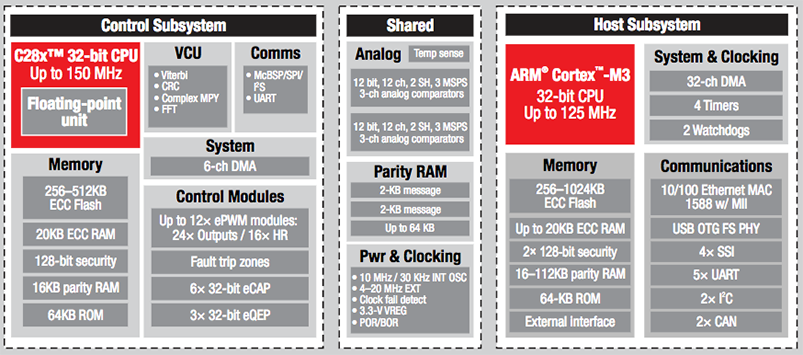
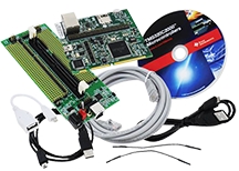
TMDSDOCKH52C1 Experimenter Kit for the F28M35H52C1 microcontroller
The F28M3x has a variety of peripherals suitable for the intended applications. These include analog, control, and communication peripherals. The C28x core helps implement real-time control, sensing, and DSP filtering, as well as processing. A Viterbi Coding unit in the core helps implement power line communication. Motor control and power monitoring are some important areas of industrial application that these devices can address. They can support an OS. Scheduling is implemented. They also support a range of communications protocols that include Ethernet, USB, CAN, UART, SPI and I2C.
- 5.3.2 TM4C12x MCUs
The MCU products from the TM4C12x Series of the control + automation family has the popular ARM Cortex-M4 core. This family offers a range of memory options. There are several package options too. These devices also offer sophisticated analog integration as well as a large set of connectivity peripherals. This family, also known as the Tiva C Series, and helps create solutions in sensor hubs, displays, networking and industrial automation.
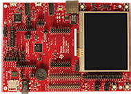
IoT Enabled ARM Cortex
 -M4F MCU TM4C129X Connected Development Kit
The TM4C129x MCUs devices within the TM4C12x family have built-in Ethernet MAC+PHY layers. They are useful in creating highly connected products that can communicate with the cloud and the Internet. In the industrial space, this capability helps create products in the Industrial Internet of Things (IIoT). Along with on-chip data protection and an LCD controller, it is possible to create not only IIoT gateways, but also connected HMI products, building automation products, sensor gateways, etc. Motion control applications are feasible too.
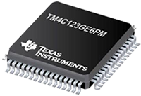
TM4C123GE6PM Industrial Microcontroller
A variant of the TM4C12x family is the TM4C123x MCUs devices. They offer a configuration that has built-in USB support and CAN support thus are useful in the automotive domain. They integrate ARM's Cortex-M4F CPU with single-precision floating-point core. Operating frequencies can go up to 80 MHz. These devices may draw as little as 1.6 μA in a low power mode. The device offers 40 PWM outputs and many serial communications peripherals. Support of USB, OTG, and two CAN controllers are also available. The TM4C123x MCUs are a good fit for applications such as home, building, and industrial applications.
- 5.4 Safety MCUs: The Hercules Family
Many industrial, automotive, and medical applications must have safety features built-in for critical operations in the control loops these MCUs are assigned to process. Threat to the safety of the operator, user or bystander may arise when critical operations in the whole sequence of the software process fails. For example, in a motor control operation, there could be a failure that causes a complete runaway of the motor, which is a potentially dangerous situation. A failure in an industrial assembly robot may cause damage to parts being manufactured. An anti-lock brake system may fail, affecting the safety of passengers in an automobile. Problems can happen when an airbag deployment fails. The implication is that, should a failure occur in the hardware or the software of the system, it should be possible to immediately detect and take remedial actions. The Hercules family is positioned to address such safety critical applications. The products based on the Hercules family will help the product in obtaining certification to safety regulations such as IEC 61508.
IEC 61508 is an "umbrella" document covering multiple industries and applications. The standard’s primary goal is to let individual industries develop supplemental standards for their domain. On a secondary level, IEC 61508 helps in the development of Electrical/ Electronic/Programmable Electronic (E/E/PE) safety-related systems for an industry where one does not exist already. The 61508 standard covers safety systems that have mechanical/electrical/electronic/programmable electronic devices.
The first version of the IEC 61508, published in 1998 was entitled "Functional Safety of Electrical/Electronic/Programmable Electronic Safety-Related Systems,". ISO 26262 applicable to the automotive industry was published in 2011 as "Road Vehicles—Functional Safety". "Functional Safety" is defined as a safe state brought about by the operation of the E/E/PE systems. Typically, a Safety Integrity Level (SIL) is associated when determining compliance with the safety standard 61508. There are 4 levels and a SIL level is defined to be a relative level of risk-reduction provided by a safety function. SIL 4 provides the highest level of risk reduction, while SIL 1 provides the least amount. Industrial systems are often required to comply with IEC-61508 SIL3 or better.
Compliance of end equipment with the functional safety standards are assessed by independent agencies such as TUV and Underwriters Lab (UL) and tend to focus on aspects of the product design as follows:
- Product development safety life-cycle, the prevailing safety culture in the development team and the company hosting the team. Development and ancillary processes are also looked at closely.
- How are the random failures managed?
- How does the company manage predictable and systematic failures?
TI also provides documents that help understand the standards IEC 61508 and ISO 26262. Steps to achieve compliance through the use of certified MCUs are also documented. Development flow that ensures product safety and the means to reduce failures are offered. These documents discuss proper safety development work-flow and how one could reduce failures in a piece of equipment.
A major feature of the Hercules architecture is the lock-step operation of an independent CPU that executes the same instructions in parallel. On-chip comparators compare the outputs to decide whether the instruction has been executed (i.e., when both outputs compare). When results differ, it clearly indicates a fault in one of the processor cores and alerts are raised so that the safety systems can operate such that the system can be brought to a safe state. The programmers still see this as a single processor, single instruction issued processor. There is no need to be conscious of the shadow processor.
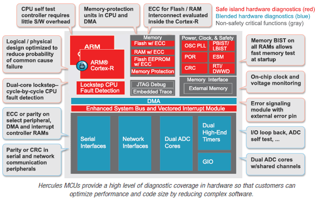
TI offers a SafeTI package of software and documentation that help in the compliance effort. These include a compliance support package that helps development and review of safety compliant software for the MCU. A whole set of diagnostics need to run to ensure the health of the main processor, as well as the shadow CPU; TI provides an extensive MCU diagnostics library. Peripheral drivers are also safety critical and TI offers hardware abstraction layer code generator (HALCoGen) peripheral drivers to help build safe drivers. A GUI-based software-test automation unit (TAU) provided is useful for testing out your software for compliance.
Hercules MCU devices are available in two families, both are ARM Cortex -R based.
Hercules RM MCUs
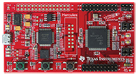
Development Board for RM42X Series of Hercules Microcontrollers
Hercules 570 MCUs
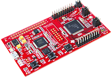
Development Board for TMS570 Series of Hercules Microcontrollers
The 570 family is positioned mainly for the automotive market. The RM family (RM 57, RM 48, RM 46, RM 44 and RM42/41 devices) addresses industrial safety applications in the following areas:
- Industrial Automation and Control
- Power Inverters and Generators
- Programmable Logic Controllers
- Turbines & Windmills
- Robotics
- Industrial Drive Monitoring
The devices in this family are:
- IEC 61508 SIL 3 certified
- Operating speed range from 80 MHz to 330 MHz
- Operating temperature can go up to 105 degrees Celsius
- Communication capabilities include Ethernet, USB, CAN, timers, ADCs and more
6. C2000 MCU Industrial Drive Solutions
Industrial drive solutions are quite complex when you factor in the diverse motor types. This is compounded by the fact that several position encoder standards exist. Sensing technologies that sense magnetic flux, current, back EMF and so on, keep evolving. An additional factor is the changing scenario of industrial communications. TI makes a diverse array of tools, documentation and other forms of support to help designers/developers create industrial drive solutions.
Some example application areas will indicate how diverse the need for motors and their control can be. These include industrial robots, servo drives, elevators, CNC machines and AC inverter drives, among others. TI offers a package of product support tools that help developers work on industrial drive solutions such as the "DesignDrive" package, which has 4 components:
- A hardware demo/development board in the form of a "Launchpad"
- The "DesignDrive" software product. This is a part of the general package controlSUITE
. It contains necessary drivers and libraries, and a lot of code examples that use the powerSUITE & DesignDRIVE software. The package components take care of control, sensing, positioning management, isolation, bias power, diagnostics, as well as safety.
- Reference designs are available through TIDesigns. This package contains Industrial Servo Drive and AC Inverter Drive Reference Design, as well as an EtherCAT Interface for High Performance MCU Reference Design.
- The 4th component is a package of on-line training material.
Overall, this package helps by offering development tools that reduce time-to-market significantly. The tools help debug the code on actual representative hardware even when your customized boards may not be ready. The reference designs help speed up hardware design.
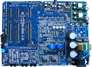
C2000 DesignDRIVE Development Kit for Industrial Motor Control
The DesignDrive package is a complete tool for developing all kinds of industrial drives. This overall package facilitates your drives and servo control development and/or evaluation. It provides examples of good designs in control of motors. The controls include management of torque, position, and speed. The design examples illustrate more than one form of current sensing topologies. It will let you incorporate a position sensor interface that is analog or digital. Another need of any collaborative large system is real-time connectivity, which is also supported.
Low latency, jitter, and high precision in designs is supported through an MCU with sufficient horsepower, relevant peripherals, and serial communication connectivity. EtherCAT, CAN Open and Powerline Communication are supported by the solutions provided. Each of these communication software stack operates through hardware abstraction layers (HAL). As these software support stacks are provided as part of the solution, development and implementation of these protocols are minimized.
*Trademark. Texas Instruments , and TI are trademarks of Texas Instruments, Inc. Other logos, product and/or company names may be trademarks of their respective owners.
Test Your Knowledge
Microcontroller Skills 3

Are you ready to demonstrate your industrial microcontrollers knowledge? Then take a quick 15-question multiple choice quiz to see how much you've learned from this Essentials MCUs 3 module.
To earn the MCUs 3 badge, read through the module to learn all about industrial microcontrollers, attain 100% in the quiz, and leave us some feedback in the comments section.

Top Comments
-

mudz
-
Cancel
-
Vote Up
+1
Vote Down
-
-
Sign in to reply
-
More
-
Cancel
-

phoenixcomm
in reply to mudz
-
Cancel
-
Vote Up
+2
Vote Down
-
-
Sign in to reply
-
More
-
Cancel
Comment-

phoenixcomm
in reply to mudz
-
Cancel
-
Vote Up
+2
Vote Down
-
-
Sign in to reply
-
More
-
Cancel
Children