1. Introduction | 2. Objectives | 3. Basic Concepts | 4. Analysis and Applications | 5. Glossary | Related Components | Take the Quiz
A relay is an electronically operated switch that is remotely activated by an electromagnet. When the electromagnet is powered, it generates a magnetic field, which controls a set of contacts that either make or break a circuit. Relays are found in a variety of applications where resistive, inductive, and capacitive loads need to be controlled. Relays are also ubiquitous in applications supporting many modern industries, including telecommunications, automotive, power, and robotics. This learning module discusses the basics of relays, the various types of relays, design considerations, and use case applications.
2. Objectives
Upon completion of this module, you will be able to:
- Describe the use of relays
- Understand the basic concepts and operation of relays
- Discuss the different types of relays
- Explain the integration of relays into the design of various applications
Relays have the same principle of operation, regardless of what type they are. They first convert an electrical input signal on the primary side to an intermediate and non-electrical physical signal. This signal is used to operate a switching element, such as moveable contacts, on the secondary side, making or breaking a connection that conducts electrical current. A simple electromagnetic relay consists of a wire coil wrapped around a soft iron core, an armature, and assembled contacts. When an electrical input signal is present, current flows through the coil, generating a magnetic field. The magnetic field physically pulls the armature, mechanically pushing one of the moveable contacts, making or breaking a connection.
- 3.1 Function
Relays provide a variety of benefits. With their ability to activate multiple circuits and functions, relays can handle the duties of multiple high current capacity switches, increasing cost savings. Relays also provide galvanic separation between input and output. Relays are also able to perform simple logic functions, such as latching an output on or off from a momentary input. Some of the main functions of relays include:
- Galvanic separation of the primary or actuating circuit and load circuits
- Single-input/multiple-output capability
- Separation of different load circuits for multi-pole relays
- Separation of AC and DC circuits
- Interface between electronic and power circuits
- 3.2 Contact Configurations
As shown in Figure 1, there are three types of contact configuration: Form A, Form B, and Form C. Form A represents a Single Pole Single Throw (SPST) connection, with the contacts normally open (NO) when the relay coil has no current running through it. Form B is also an SPST connection; however, if the relay coil is not energized, the contacts are normally closed (NC). Form C, otherwise known as changeover, represents the Single Pole Double Throw (SPDT) connection, and has three contacts: Common (Com), NO, and NC. The name "changeover" is given, as the common contact changes from the NC to NO contact when the coil is energized.

Figure 1: Various contact configurations available in relays
Relays are also available with multiple contacts, having a variety of configurations, including DPDT (Double Pole Double Throw), 3PDT (Three Poles Double Throw), DPST-NO (Double Pole Single Throw-Normally Open), and DPST-NC (Double Pole Single Throw-Normally Closed).
- 3.3 Relay Types and Comparisons
There are several types of relays, differentiated by their structural features and operating principles.
Unlike the aforementioned electromagnetic relay (EMR), a Solid-State Relay (SSR) lacks moving parts, instead employing electronic switches, such as transistors and triacs, as their principal switching elements. An SSR uses the solid-state semiconductors' electrical and optical properties to execute its input to output isolation and switching functions. Figure 2 illustrates an optocoupler, an example of an SSR, with an input and output circuit.

Figure 2: An example of a solid state relay
Compared to an EMR, SSRs have a longer lifespan, due to their lack of moving parts, and they are more compact. Additionally, SSRs react faster than typical EMRs, which require 5-20ms to switch, whereas an SSR takes 0.25-10ms. However, EMRs are much simpler devices, are less expensive, and can better endure misapplication or misuse compared to SSRs. Troubleshooting is also easier with an EMR. SSRs perform better in environments with strong electromagnetic interference, while EMRs have better thermal performance.
A typical signal relay has a secondary molded coil, which offers high insulation performance between the contact and the coil. It switches signal, voice, and data up to a 2A resistive load. The different types of signal relays include Yoke-type relays, reed relays, and solid-state relays. Signal relays are typically found in measurement systems, telecommunication equipment, and computer interfaces.
Power relays, in contrast, can typically switch up to 600V and 100A, thus overlapping the switching range of contactors. General-purpose power relays use the pulse width modulation (PWM) control scheme, which is an effective means of improving efficiency and thermal performance.
When there is no power applied to the coil circuit, non-latching (monostable) relays stay in a single OFF or unenergized stable position. When power is applied, the magnetic force generated by the internal coils switches the relay to the energized ON position. When the power is turned off, the relay reverts to its unenergized position. This behavior makes a non-latching relay suitable for use in push-button applications like micro-controller input buttons.
While non-latching and latching (bistable) relays are similar in design and function, the major difference is that the latching relay remains in its last powered position. Latching relays have two stable positions: ON and OFF, and the positions are retained until they are reset. To reset a latching relay, an additional signal must be applied: a reverse polarity voltage for a single coil latching relay, and energizing a second coil in a dual coil latching relay. Bistable relays have two advantages: zero power consumption after switching, even with the relay maintaining its switched state for prolonged periods, as well as the fact that the non-energized relay coil generates no heat, helping the system achieve better thermal performance.
A single coil latching relay uses one coil to control the contacts. Energizing the coil with a voltage sets the contact. To reset the contact, a reverse polarity voltage must be applied to the coil. The simplest way to control a single coil latching relay is manually via push button.
A more elegant solution is the “C”-circuit. In the “C”-circuit, a capacitor is placed in series with the relay coil. When voltage is applied to the coil, the capacitor (initially discharged) begins to charge. The relay is set as the coil is energized. As the capacitor charges, the current decreases, dropping to almost zero when it is fully charged (only leakage current through the capacitor remains). The coil voltage can continue to be applied, however, and the current is almost zero, enabling very low power consumption. This is illustrated in Figure 3a.
To reset the “C”-circuit, the coil circuit simply needs to be opened and shorted to the coil’s ground potential. The capacitor now becomes the power source as it discharges, driving a current pulse with opposite polarity through the coil. This resets the relay, as shown in Figure 3b.

Figure 3a

Figure 3b

Figure 4: Dual coil latching relay. Source TE Connectivity
Dual coil latching relays are controlled by two different coils, as shown in Figure 4. Voltage is applied to either the Set coil or the Reset coil to perform the required action. Having two individual coils for each action requires two power sources or drivers, however, it also enables this type of relay to be driven by two independent circuits.
Integrated manufacturing (IM) relays from TE are versatile, with small form factors, making them good choices for applications requiring increasingly smaller electronic components with similar performance capacities of standard-sized parts. The components that make up the IM relay are surrounded by a plastic resin, or overmolded, into an insulated package. Critical electrical connections are protected by the plastic resin, giving the relay high shock resistance.
The overmolding technique enables high performance at a minimal size. The IM relay is well-suited for modern devices, where available space is becoming more and more scarce. Unlike other relays, the IM relay can switch both signal and power. It is also able to switch power loads and deliver high performance capable of switching a current of up to 2-5A at 60W.
They offer a reliable and efficient switch signal, as well as low power consumption, in a low-profile design. Their minimal coil power consumption supports high-density relay applications by reducing overall power consumption. They are engineered for high shock resistance, which is the result of how the relay is molded, mounted, and fixed together during the assembly process. The shock-resistant design can withstand shocks of up to 300 g’s, making them feasible solutions for industrial applications. IM relays support multiple contact configurations and are well-suited for high-volume applied technologies, such as automotive infotainment systems, communications equipment, and consumer electronics.
IM relays can support battery-powered applications, and they are available in a range of contact structures with a lower cost impact when compared to a solid-state relay. Because they do not need power to maintain state, a bistable relay can reduce power consumption.
- 3.4 Relay Selection
Because there are so many types of relays with such a large range of specifications, it is essential to choose the right relay for the job. Various factors should be considered when selecting a suitable relay for a specific application, including:
- Operating supply voltage
- Number and type (configuration) of contacts
- Voltage and current rating of contacts
- Voltage and current rating of the coil
- Isolation between coil circuit and contacts
- Suitability for harsh environments
- Safety considerations: the package should be touch-safe and explosion proof
- Mounting options—examples include sockets, plug, PCB, rail mount, panel mount, or enclosure for mounting on walls or equipment
- Switching time (in applications where high speed is required)
When using a relay in various applications, we need to consider multiple factors, including the type of circuit that drives the coil, the type of load that the relay switches, requirements for size and form factor, and desired contact-load performance. We will analyze and discuss design considerations with a few TE-specific relays and use case applications.
- 4.1 Coil Voltage and Temperature Compensation
Relay coils are usually wound using copper wire with a positive temperature coefficient. Most coils are powered by a relatively constant voltage and, thus, a temperature increase results in higher coil resistance and decreased coil current. The magnetic field strength of the coil is directly related to its ampere-turns (ATs), the current in amps multiplied by the number of turns in the coil. A fixed voltage and increased temperature yield decrease AT, resulting in decreased magnetic field strength. For reliable operation, sufficient AT must always be maintained, even under worst-case conditions.
The current in the DC coil is determined by the applied voltage and the coil resistance. The coil current decreases with a decrease in voltage or an increase in resistance - resulting in lower AT and reduced magnetic force in the coil.
The current in the AC coil is influenced by the coil impedance and applied voltage. Changing the coil resistance, however, has slightly less of an effect on AC coils than their DC counterparts, as impedance includes reactance as well as resistance. Impedance is defined as Z = sqrt(R2 + XL2 ), where XL is the inductive component of the circuit’s reactance. The applied coil voltage also varies as the power supply fluctuates over time. A voltage range must be defined (typically +10%/-20% of nominal) for which proper operation is supported by the control design.
Coil resistance also changes with temperature; useful formulas for calculating coil resistance change over temperature are as follows:
Rf=Ri((Tf + 234.5)/(Ti + 234.5))
Where:
Ri = Coil resistance at initial coil temperature
Rf = Coil resistance at final coil temperature
Ti = Initial coil temperature
Tf = Final coil temperature
Tri = Ambient temperature at start of test
Trt = Ambient temperature at end of test
Vo = Original "operate" voltage
Vf = Final operate voltage (corrected for coil temperature change)
- 4.2 Improving Load-life Performance for DC Coils Switching AC Loads
Motors, solenoids, and other applications where DC coils switch AC, inductive, and capacitive loads can have initial surge currents as high as 10 times the steady-state current when energized, often leading to welded contacts. Oversized or specially designed relays are usually needed to manage this high inrush current. When opening contacts, the breaking contact arc between them usually extinguishes only when the high-current sine wave transitions through zero and reverses polarity. Because of these characteristics, contact closure and opening should be synchronized with the AC voltage or current signal, in this manner:
- Make: Closing (or making) a contact should be synchronized with the zero-crossing of the voltage waveform.
- Break: Opening (or breaking) a contact should be synchronized with the zero-crossing of the current waveform.
There are various ways to enhance relay performance when switching some load types by synchronizing the "make" and "break" timing to the AC voltage and/or current sine-wave. The following content discusses some of these techniques and their advantages and limitations.
When the contact closure is synchronized with the zero-crossing point of the voltage waveform (typically right before or right after), the relay contact does not have to deal with a significant current or voltage. This increases contact life. The ability to handle loads with high starting currents is also improved, because at the moment of contact, voltage and current are low and typically will not ramp up to maximum peak current before the relay contact has stabilized. Relays can be operated in this manner by driving the relay coil, so that the relay contact closes or “makes” just before or after the zero point (usually +/- 1 millisecond is acceptable and achievable). To ensure timing accuracy, the operate time of the relay must be added as an offset.
As an example, Figure 5 illustrates energizing a 1/10hp Inducer Fan Motor at 0° on the voltage waveform. A high first half-cycle current surge occurs because the voltage is not 0V.
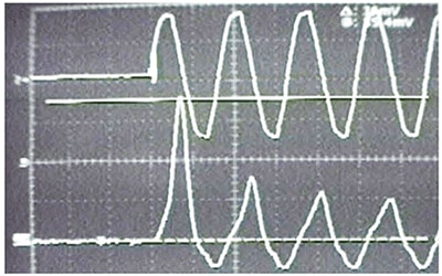
Figure 5: Fan motor energized at 0° on the voltage waveform (the top waveform is voltage, the bottom waveform is current). Source: TE Connectivity
Figure 6 shows the same Fan Motor being energized at 90° on the voltage waveform. Because this coincides with the zero-crossing of the voltage waveform, no current surge takes place. Typically, the best make point is about 75° before the peak for most inductive loads. The exact value is not critical, and anything within the 70-90° range is generally acceptable.
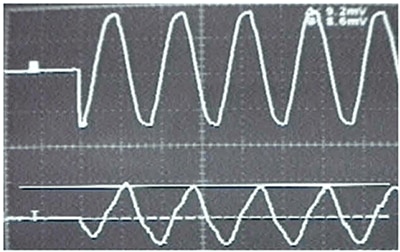
Figure 6: Fan motor energized at 90° (the top waveform is voltage, the bottom waveform is current). Source: TE Connectivity
Breaking the contact is similar to making it; when the contact opening is synchronized to right before the zero-crossing of the current waveform, the arc will be extinguished at the zero-crossing. This greatly reduces contact erosion and wear. For non-inductive loads, where there is no phase differential between voltage and current, breaking at the zero-crossing of the voltage waveform is acceptable, making the design of the system simpler.
Examining the surface of a relay contact under a microscope reveals a surface that isn’t very smooth; some points are higher than others. When the relay contacts close, the first high spot on the surface will make contact first. In that moment, this tiny point is subjected to the full load current. Even with a current that is a fraction of an ampere, the heat generated may cause that high spot to melt in an instant. The air around the high spot is heated and begins to lose electrons and ionize. If there is sufficient power, the high spot may reach 5000 degrees Kelvin or more and potentially explode, resulting in superheated, ionized air and metallic ions filling the gap between the contacts. This ionized air may lead to an electron current between the cathode and anode; the beginning of an arc. If the current is greater than the arc current rating of the contact material, the arc will be able to sustain itself.
Figure 7 illustrates an arc suppression circuit. A capacitor is effective at suppressing the arc; however, it will discharge the stored energy through the relay contacts. To limit this potentially large discharge current, the circuit should have resistance in series.
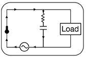
Figure 7: Arc suppression circuit (RC Circuit) with relay contact. Source: TE Connectivity
- 4.3 PCB Design Tips for the AXICOM HF Relay Family
AXICOM HF Relays perform well at high frequencies, due to their design and electromechanical nature. In order to maintain efficient performance throughout the entire system, designing the PCB requires careful consideration. Low insertion loss, low return loss, and high isolation are goals in the design of the PCB. As frequency and/or power increase, reaching these goals becomes more critical.
Material selection for the dielectric and conductor in the PCB is a factor when trying to achieve low insertion loss. The dielectric should have a dielectric constant (εr) that is as homogenous and constant with frequency as possible, as well as a low dielectric loss tangent (δ). A δ value ≤ 0.005 is recommended for good insertion-loss, with ≤ 0.0015 recommended for excellent insertion-loss. Typically, dielectric materials with a low dielectric constant (εr) are preferred. The conductor must have an excellent conductivity (σ). PCBs typically use copper. To prevent oxidation, exposed copper surfaces must be protected, either by coating (dielectric) or passivation (conductor). The width of the traces should be kept high to maintain low insertion loss.
Return loss can be minimized by designing the the traces to reduce reflections of the signal. Reflections can be caused by improperly designed transitions and curves. Figure 8 illustrates the design that best minimizes return loss through the transition or curve.
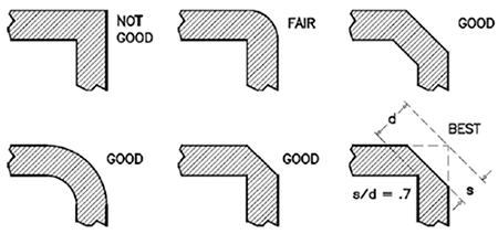
Figure 8: Recommended trace transition or curve in PCBs
Preventing unwanted signals from radiation and reflection is crucial in high frequency and high power applications. Isolation can be improved with the following measures:
- Traces should not run parallel and close to each other for lengths over λ/10.
- Traces should not be routed under the relay.
- When traces need to be crossed in different planes, they should be crossed at 90° angles.
- Grounding should be done via holes between the traces, around the pads, and under the relay. The input ground should not be the same as those of the outputs.
- Unused coil terminals must be grounded.
- Shielding may improve isolation results.
- 4.4 Applications
Relays are used in a wide variety of applications, from industrial to commercial, low to high power, and low to high frequency. We will now discuss some example applications utilizing relays.
Offline/Standby-type Uninterruptible Power Supply
Relays, such as the TE Connectivity Schrack PT270012, can be used to switch power sources in an offline/standby-type Uninterruptible Power Supply (UPS). When power from the AC mains fails, the coil in the relay is no longer energized. The contact switches positions, connecting to a battery through an inverter. The inverter converts the DC power from the battery to emergency AC power. Another relay is used to connect or disconnect a battery charger from the battery on AC mains failure.
Figure 9 illustrates a basic block diagram for an offline/standby UPS.
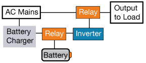
Figure 9: Offline/Standby-type UPS Block Diagram
RF Switch Using Axicom High-Frequency Relays
An RF (radio frequency) or microwave switch routes high-frequency signals over different transmission paths. Microwave test systems routinely use them to route signals between Devices Under Test (DUTs) and instruments. A myriad of signals from multiple instruments are routed to one or more DUTs via a switch within a switch matrix system. This arrangement enables several tests to be performed with a single setup, eliminating the need for frequent connecting and disconnecting. The complete testing process is automated, thus increasing throughput in high volume production ecosystems.
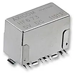
Axicom High Frequency (HF) relays provide a reliable solution for the switching of radio-frequency applications of up to 6 GHz. A careful design is needed to achieve low insertion loss, low return loss, and high isolation, or an acceptable combination of the three. Figure 10 shows the Axicom HF6-93 Series general purpose high-frequency relay. Its contact configuration is 1 Form C (1CO). HF6-93 Series relays operate in the DC to 6 GHz frequency range and have a 50 Ω impedance. They are energy efficient (power consumption below 150mW) and have a small form factor (16mm X 7.6mm X 10mm).

- Bounce: A phenomenon where the contact elements touch and separate repeatedly before they settle into their final position.
- Bounce Time: The time needed for contacts to come to full rest after a make. Unless otherwise stated, bounce times are specified as maximum values. They correspond to energization at the rated voltage, without any components in series or parallel to the coil, and at the reference temperature.
- Make-Before-Break: A contact mechanism where the center contact makes the new connection before it breaks the old one, meaning that it is momentarily connected to both contacts.
- Coil Power: The power consumption of the coil at its rated coil voltage and coil resistance at reference temperature.
- Coil Resistance: The electrical resistance of the relay coil at reference temperature; this value is indicated for the coil without any other devices in parallel (e.g., coil suppression, diode, etc.).
- NC Contact: Normally Closed Contact, a contact that is normally closed when the coil is not energized.
- NO Contact: Normally Open Contact, a contact that is normally open when the coil is not energized.
- Coil Suppression Circuit: A circuit designed to reduce the inductive switch-off voltage peak of the relay coil.
- Coil Voltage: The voltage applied across the coil terminals.
- Reset: The process in which a bistable relay returns from the operate state back to the rest state, or where the switch position returns to that of the unenergized state.
- Coil Voltage Range: The voltage range at which the relay shows its operating characteristics.
- Creepage Distance: The shortest distance along the surface of the insulating material between two conductive parts. In high powered applications, if two conductors are too close together, they can arc to one another.
- Contact Resistance: The electrical resistance between the relay terminals of a closed contact, measured with indicated measuring current and source voltage.
- AC (Alternating Current): An electric current that periodically reverses direction and changes its magnitude with time. AC is used to transmit power because it is able to travel long distances without a great loss of energy to resistance.
- DC (Direct Current): A one-directional flow of electric charge.
- Insertion Loss: The loss in load power due to inserting a component at some point in a transmission system.
- Return Loss: The ratio of reflected power to the launch signal.
- SPDT (Single Pole Double Throw): A switch with a single input that can connect and switch between two outputs.
- DPDT (Double Pole Double Throw): A switch with two inputs and four outputs. Each input can connect to two corresponding outputs.
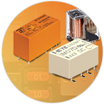
Listed are a variety of signal and power relays available from TE Connectivity.
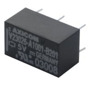
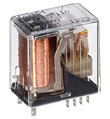
The V23026-A1001-B201 is a 5 VDC, SPDT, 1A, through hole, monostable signal relay from the P1/V23026 series signal relays. These relays are used in CAN bus, immobilizer, office equipment, measurement, and control equipment.
The 8-1393808-3 is a 24 VDC, 4PDT, 2A, through hole, non-latching signal relay from the Cradle N/V23154 series. The Cradle-N Signal Relays have various contact arrangements and materials to meet specific applications. Operating voltage is 1.5 to 125VDC/AC. Latching and non-latching coils are available on request.
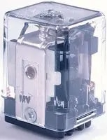
is a general-purpose Panel Plug-in Relay with DC coil. This KUP-series relay has 3 form-C (3PDT) AgCdO contacts. 4.75mm (0.187-inch) quick-connect terminal, bracket mount case. Class B coil insulation. It features an enclosed relay, wide selection of termination and mounting styles, No Au flashing on contacts, -45 to 70°C Operating temperature range and RT I Environmental protection rating. Commercial.
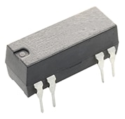
The Axicom Reed Relay V23100 V4024A011 is a signal relay that features 24 VDC contact voltage, 288 mW Coil Power (DC), PCB-THT, 24 VDC coil voltage, and a 1A current rating.
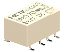
The Axicom Reed Relay V23100 V4024A011 is a signal relay that features 24 VDC contact voltage, 288 mW Coil Power (DC), PCB-THT, 24 VDC coil voltage, and a 1A current rating. The IM07DGR is a signal relay from the Axicom IM series that features a 220 VDC contact voltage, 250 VAC Contact Voltage, 200 mW Coil Power (DC), PCB-SMT, and a 5A current rating.
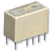
The V23079B1205B301 is a 2-pole signal relay with DC coil, 2 Form C (2CO) contact configuration, and AgNi+Au contact. It has a slimline 15 x 7.5mm (0.590 x 0.295-inch) form factor and is immersion cleanable. Power consumption is low (140mW/70mW) with high sensitivity. This relay can be used in Industrial, power management, automation, consumer electronics, and medical applications.
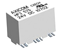
HF353 is an HF3 series signal relay having a frequency range of DC to 3GHz and an impedance of 50 Ω or 75 Ω. It is available in a small form factor (14.6x7.2x10mm) with 1 Form C contact configuration (1 changeover contact). It is immersion cleanable and has low power consumption (≤140mW). This relay is well-suited for use in cable modems, line cards/ CATV, Tabs, measurement and test equipment ATE, satellite/audio/video tuners, wireless base stations, antennas, and switching boards.
For more variety of relay products Shop Now
Take the QuizBack to Top

Are you ready to demonstrate your Relay Technologies knowledge? Then take this 10-question quiz. To earn the Relays I Badge, read through the module, attain 100% in the quiz, and leave us some feedback in the comments section.


Top Comments
-

koudelad
-
Cancel
-
Vote Up
0
Vote Down
-
-
Sign in to reply
-
More
-
Cancel
Comment-

koudelad
-
Cancel
-
Vote Up
0
Vote Down
-
-
Sign in to reply
-
More
-
Cancel
Children