 Sensors Series - Part 8 - Industrial HVACR
HVACR systems regulate climate and maintain the temperature, ventilation, airflow, and air quality in an indoor environment. They are present in industrial, commercial, institutional, residential buildings, and vehicles. The primary goal of an HVACR system is to make residents feel comfortable, healthier, and more productive in a closed environment.
HVACR systems use various sensors to continuously measure and control process variables, such as heat, humidity, and gaseous air pollutants; elements that are responsible for creating an undesirable environment. The measurements produced by the sensors are transferred to a central processing unit (CPU) or microcontroller unit (MCU), where they can be evaluated, and next steps determined. This learning module discusses the fundamentals of an HVACR system and the different sensors used in the HVACR. It will also cover their working concept, varieties of systems, and a few applications.
Related Components | Test Your Knowledge 
sponsored by
2. Objectives
Upon completion of this module, you will be able to:
- Describe an HVACR system and its control system
- Understand the basic concept and operation of an HVACR system
- Discuss the sensors used in HVACR control systems
- Explain applications of different sensors in the HVACR control system
3. Basic Concepts
HVACR is the abbreviation for heating, ventilation, air conditioning, and refrigeration. HVACR systems contain various mechanical, electrical, instrumentation, and control components to provide heating and cooling, indoor climate control, and air quality. An HVACR system uses thermodynamics, fluid mechanics, and heat transfer principles at different steps in the system’s operation. The following content discusses a typical system configuration.
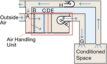
Figure 1 illustrates a standard HVACR system where external air enters through an air duct, mixing with the returning air from inside before reaching the filters. The mixed air is pulled through filters (B) to remove particulates and gaseous pollutants. The moving air then flows over a set of cooling coils (C), where it is cooled and potentially dehumidified. The air then rushes past heating coils (D) that, if necessary, heat it to the required temperature. This heated air then passes over a set of humidification tubes (E), which add any necessary moisture. The air, post humidification, is pulled into the supply fan (F) and pushed through the diffusers (G) into the supply ductwork and space. The return fan (H) then pulls air from the conditioned space and forces it through the return ductwork. Finally, the air is exhausted outside or is returned to the unit and mixed with fresh air to begin the cycle again.
A cooling source, such as a chiller or cooling tower, feeds the cooling coils (C). A refrigerant, a specialized chemical compound such as hydrofluorocarbons (HFCs), enters the cooling coils, absorbs heat from the air passing over the coils, and returns to the source to desorb its heat. A heating source, such as a boiler, transfers heat to the heating coils (D), which transfers heat to the air passing over them.
The following will cover some important components of HVACR systems and their uses:
Heat Exchanger – The heat exchanger in an HVACR system transfers thermal energy from one fluid (either a liquid or a gas) to another without mixing the two. A solid wall (with high thermal conductivity) separates the fluids to prevent any mixing. Thermal transfer occurs via a variety of methods, including conduction, convection, or radiation.
Blower – An electric blower is a fan that forces warm air into the ductwork and the enclosed volume. A blower typically starts and stops when the temperature sensor detects the air has reached preset temperature thresholds. Flow sensors continuously measure the flow at different stages and provide feedback to maintain the desired flow rate.
Combustion Chamber – The combustion chamber is the area where the fuel/air mixture ignites. Ignition is caused by an ignitor; a pilot light in older furnaces and an electronic starter in newer ones. This ignition begins the heating cycle within the furnace.
Compressor – A compressor keeps the refrigerant moving through the refrigeration system. It does so by squeezing (or compressing) the refrigerant, increasing the pressure of the gas and raising its temperature. The high-pressure gas is then forced into the condenser coils, releasing the heat and humidity.
Evaporator Coil – An evaporator coil is a component in an air conditioner that absorbs the heat that the refrigerant is carrying. Evaporator coils are typically made from copper or steel, metals that conduct heat well. The absorbed heat is released outdoors through the condenser coils.
Thermostat –A thermostat is a device that monitors the temperature and adjusts the heating or cooling system in an HVACR system to regulate the temperature. Thermostats use different types of temperature sensors. For example, some thermostats use bimetallic strip temperature sensors, operating as electrical switches to control the heater and air conditioner.
- 3.1 HVACR Control System and Use of Sensors
The control system governs the various heating and air conditioning operations. Measurements, such as temperature, pressure, and air quality, are received from the sensors and compared with desired values. This data helps to make adjustments within the system. Hybrid control systems combine self-powered, electric, pneumatic, analog, electronic, and digital controls.
Figure 2 illustrates a typical HVAC closed-loop control system where an air-heating system uses a heating coil paired with a heat source. A fan pushes the cold air through the system and heats it to the desired temperature.
The sensor monitors the temperature of the inflow air to the controller. The measured temperature (control point) can differ from the controller's desired temperature (set point). The difference between the set and control points is called the error. The controller uses the error to calculate an output signal and transmit that signal to the valve (the controlled device or actuator).
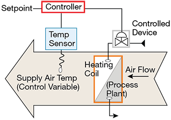
Figure 2: Closed-Loop Control in a Simple Heating System. Image Source: Fundamentals of HVACR Control Systems
Identical methods are used to monitor process variables such as humidity, flow, and pressure. Data from sensors allows the various components of an HVACR system to be controlled. We will discuss a few sensors used in an HVACR system.
Temperature Sensors - Temperature sensors are components that measure the temperature. Various temperature sensors are available, including thermistors, infrared (IR) sensors, and thermocouples, and are selected based on application requirements. Different temperature sensors have different working principles. A thermistor, for example, changes its resistance with a temperature change. This resistance change can be converted into an accurate temperature measurement.
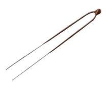
Figure 3: Thermometrics Type CR1 NTC temperature sensor (Amphenol Advanced Sensors)
Thermometrics Type CR1 NTC Chip Thermistors consist of NK Type NTC Thermistors, which have Tin (Sn) coated Alloy 52 leads, with a high-performance acid and moisture resistant coating. They are ideal for harsh environment applications.
Pressure Sensors - A pressure sensor converts pressure or force into a usable electrical output signal. The internals of a pressure sensor consists of a pressure-sensitive element and a processing circuit. There are three different types of pressure sensors: gauge, differential, and absolute. Many HVACR systems use pressure sensors to measure airflow and pressure for better air distribution. Some HVACR applications include: VAV (variable air volume) control, static duct pressure, and clogged HVACR filter detection.

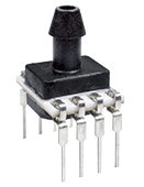
Figure 4: ELVH Series Pressure Sensors (All Sensors)
The ELVH Series Pressure Sensors are based on All Sensors' ultra-low pressure CoBeam2 TM Technology. This sensing element provides pressure sensors with ultra-low pressure sensing, which reduces susceptibility to package stress. Long term stability is improved, as well as position sensitivity. The ELVH Series communicate via digital interface, making integration with modern MCUs easy.
Humidity Sensors - Humidity sensors measure the amount of moisture present in the air. There are three basic types of humidity sensors: capacitive, thermal, and resistive. All three types monitor minute changes in the atmosphere to calculate air humidity. A capacitive humidity sensor contains a thin metal oxide strip between two electrodes to perceive relative humidity. It does this by measuring the strip's electrical capacity, which changes with the relative humidity of the surrounding atmosphere. Resistive sensors, or hygristors, make use of a polymer humidity sensing film which changes resistance as humidity changes. Thermal sensors calculate the difference in thermal conductivity of dry vs humid air, using two NTC thermistors, one hermetically sealed in dry nitrogen. The difference in resistance of the two thermistors is directly proportional to the absolute humidity.
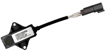
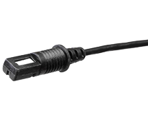
Figure 5: T9501 Humidity and Temperature Sensor (Amphenol Advanced Sensors)
The Telaire T9501 Humidity & Temperature Sensor provides humidity and temperature measurements via the industry standard MODBUS communication protocol. They are IP67-rated and designed to tolerate challenging environments. They utilize an individually calibrated and tested ChipCap 2 sensor and are ready to integrate into control/monitoring systems without further calibration or temperature compensation.
Air Quality Sensors (Gas Sensor) - Air quality sensors, or gas sensors, are devices that measure the gaseous component in the air. The list of gas sensors includes non-dispersive infrared (INDR) sensors, electrochemical sensors, and electroacoustic sensors. An HVAC system uses gas sensors to increase ventilation, improve filtration, and cleanse the air.

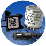
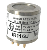
Figure 6: IR600 Series Gas Sensor (Amphenol SGX Sensortech)
Amphenol’s SGX Sensortech IR600 Infrared Gas Sensors are designed for detecting and monitoring the presence of CO2, hydrocarbons, and acetylene. Infrared gas sensors take advantage of the natural ability of target gases to absorb radiation in the infrared portion of the electromagnetic spectrum.
Position Sensors - A position sensor provides feedback on position, either absolute or relative. This feedback can then control a process or trigger an activity. Position sensors are of three classes: linear, rotary, and angular position. Several technologies are used within these different types of position sensors. Some of these technologies include:
- Hall effect-based magnetic position sensors
- Potentiometric position sensors
- Optical position sensors
Position sensor applications in HVACR systems include providing feedback for valves, actuators, and motors and building damper feedback and control.
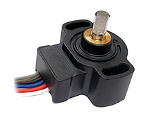
Figure 7: PSC-360 Series Position Sensor (Piher Sensing Systems)
Piher Sensing Systems' PSE Series Rotary Position Sensors are based on contactless Hall effect technology and deliver accurate measurements in a compact package. Increased rotational life and robustness against humidity, vibration, and shock make them well suited for integration into harsh industrial and transportation environments. They are absolute position sensors and keep their values, even after a power failure.
Vibration Sensor - Vibration sensors are piezoelectric sensors that measure various states of motion. There are several different types of vibration sensors, including accelerometers, velocity sensors, strain gauges, laser displacement, and gyroscopes. An HVACR system uses vibration sensors to measure the velocity and vibration of moving parts such as motors and compressors. This helps the system detect anomalies in the motion of these parts, including misalignment, worn bearings, imbalance, and other system inefficiencies.
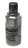
Figure 8: PC420VP-10 Vibration Sensor (Wilcoxon Sensing Technology)
Wilcoxon's PC420V series sensors provide a 4-20 mA output proportional to the vibration velocity, enabling continuous trending of vibration measurements. This trend data alerts users to changing machine conditions and helps prioritize maintenance.
Liquid Level Sensor - A level sensor is a device that measures the level of liquid or in some cases, solids, such as powders. Level sensors use various working principles, including buoyancy, capacitance, and optical methods, to obtain a measurement of level and convert it into an electric signal. Within HVACR applications, level sensors are used to measure the water level in a chilled water tank.
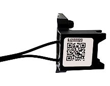
Figure 9: BAF147B002-00A0 coolant leak detector (Amphenol Advanced Sensors)
Amphenol Thermometrics' Coolant Leak Detection Sensor detects coolant leakage via a change in the resistance value of the sensor and sends a warning signal.
- 3.2 Sensor Selection Criteria
To ensure accurate, real-time, environmental monitoring, the sensors in HVACR systems require correct selection, positioning, and installation. A range of parameters can influence sensor choices for specific HVACR system applications. The selected sensor should detect the quantity under study (i.e., temperature, humidity, CO2, etc.); the expected range of values needs to be within the range of the sensor, and the sensor must have the desired accuracy and sensitivity. Some other criteria of HVACR-related sensor selection include reliability, repeatability, and precision. Output types and communication interfaces are also taken into consideration. Communication protocols like BACnet, MODBUS, and TCP/IP are required for sensors to be remotely monitored, controlled, and maintained in an HVACR system.
Commercial and residential HVACR systems often operate in harsh or challenging environments. The HVACR system requires rugged sensors that are able to tolerate large temperature swings, high moisture levels, dust and debris, and electrical noise. These sensors must have IP (ingress protection) ratings suitable for the environment they will be installed in.
4. Analysis/Applications
We will analyze how measurements from sensors installed in various parts of an HVACR system are used in its control.
- 4.1 Air Conditioning Unit
The primary goal of the air conditioning unit in the HVACR system is to extract heat from an enclosed area. The process is based on the principle of heat transfer, routing heat away from the area being cooled. This is done by changing the pressure of a low boiling point refrigerant through compression and expansion. The air conditioning unit consists of four components: compressor, evaporator, condenser, and expansion valve.
Figure 9 is a block diagram of a standard air conditioning unit. The unit is a closed-loop system where all four components receive the refrigerant through a pipeline. During circulation, the refrigerant's pressure and state change to absorb or release heat. The refrigeration cycle begins with the compressor receiving the refrigerant in a cool, low-pressure gaseous state. The compressor compresses the refrigerant into a hot, high-pressure gaseous state, after which the refrigerant enters the condenser. The heat is released externally, and the refrigerant is condensed into a low-temperature, high-pressure liquid. This refrigerant exits the condenser coil and enters the expansion valve, where its pressure is decreased. It enters the evaporator as a cold, low-pressure liquid, where it can absorb heat and cool the environment. As it absorbs heat, it changes to a low pressure gas, after which it once again enters the compressor, repeating the cycle. Temperature, pressure, and flow sensors are installed at different locations to monitor the temperature, pressure, and flow of refrigerant during this process.
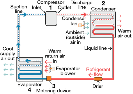
Figure 10: Air Conditioning Unit Block Diagram (Source: Kasuba, Sainath & Reddy, Mr & Nikhil, Mr & Vardhan, Mr. (2016). Flow and Thermal Analysis of Mobile Air Conditioning by using Roll Bond Evaporator). Image Source: Flow and Thermal Analysis of Mobile Air Conditioning by using Roll Bond Evaporator
- 4.2 Air Handling Unit (AHU)
An Air Handling Unit (AHU) regulates, circulates, and conditions the air. An AHU consists of input and output dampers, filters, heating and cooling coils, and blowers. Many AHUs also contain auxiliary components, such as sensors, switches, and controllers to enable automatic airflow control and monitoring of temperature, humidity, and dust.
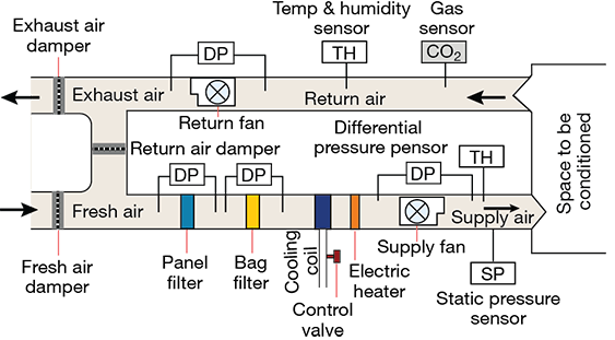
Figure 11: Air Handling Unit Block Diagram. Image Source: BMS Sequence of Operation of an Air Handling Unit with Startup, Shutdown sequence and control loops
As shown in figure 10, a running AHU mixes outside air with the inside air. This mix is then forced near the cooling and heating coils. The heating coils increase the air's temperature and maintain its humidity while the cooling coils decrease the temperature. The blower then circulates the treated air inside the workplace.
A control system (PLC/microcontroller) manages the entire AHU process. Various sensors measure variables such as air temperature, pressure, humidity, and flow, providing feedback to the controller. The controller takes action based on these feedback of the sensors.
Temperature and Humidity sensors (TH) are installed at different places, as illustrated in the figure 10, and are used to measure the air temperature and moisture at every stage. The Thermometrics Type CR1 NTC thermistor (NKA502C1R1C) and T9501 humidity sensor from Amphenol Advanced Sensors fit this application.
A gas sensor monitors the presence of CO2 in the return air and to determine indoor air quality. When the CO2 level goes beyond a set limit, the fans are turned on to increase air circulation. IR600 series or TELAiRE Series gas sensor from Amphenol Advanced Sensors (SGX SENSOR TECH) can be used for this application.
Pressure sensors (DP) installed at different locations measure the pressure difference across the filters, as well as the supply and return air pressure. When these measurements exceed a set limit, the fans can be adjusted in order to normalize air flow. The ELVH Series pressure sensors from AMPHENOL ALL SENSORS can be used for this application.
- 4.3 Pressure, Position, Level, and Vibration Monitoring in Chillers
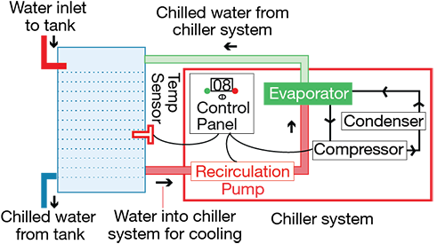
Chillers are an essential HVACR component in commercial facilities. Proper monitoring and control, in combination with preventive maintenance, ensure that the operation of a chiller is smooth. Figure 11 depicts the block diagram for a water chiller system. The vibrations of the recirculation pump can be measured with a vibration sensor, and used to detect anomalies. Level sensors can be installed on the upper and lower walls of the chilled water tank to monitor the tank's water level and control the inlet valve. Position sensors installed at the inlet and outlet provide the status of the control valve. Pressure sensors are installed to monitor water pressure in the recirculation pipe, compressor, and condenser.
A process control system like a Programmable Logic Controller (PLC) is used to receive feedback from the various sensors and control the respective device. The following sensors are well-suited for this application:
- Vibration Sensor - PC420VP-10 (Wilcoxon Sensing technology)
- Position Sensor - PSC-360 Contactless Position Sensor (Amphenol PIHER Sensors)
- Level Sensor - BAF147B002-00A0 Coolant Leak Detection (Amphenol Advanced Sensors)
- Pressure Sensor - P51-100-G-G-P-4.5V-000-000 (AMPHENOL SSI TECHNOLOGIES)
5. Glossary
- Thermodynamics/Heat Transfer Principle: Heat naturally flows from hotter to colder bodies. Heat transfer from a colder body to a warmer body can only be done through external work. HVACR systems work on the refrigeration cycle (thermodynamic cycle), where the pressure and state of the refrigerant are changed to absorb or release heat. The evaporator (cooling coil) is colder than the air flowing around it in the refrigeration cycle, thus, heat flows from the warmer air into the evaporator.
- Hall Effect: When a current-carrying conductor or a semiconductor is placed perpendicular to a magnetic field, a voltage is produced at a right angle from the current path. This effect of obtaining a measurable voltage is known as the Hall Effect.
- Piezoelectric Effect: The piezoelectric effect is the ability of certain materials to generate an electric charge in response to applied mechanical stress.
- Accuracy: Sensor accuracy is the conformity of a measured value to the actual value, or an accepted standard. Quantitatively, it should be expressed as an error or uncertainty.
- Range: The range of a sensor is the difference between the highest and the lowest operational values (limits within which a quantity can be accurately measured). This is stated by the manufacturer.
- Reliability: The reliability of a sensor is the probability that a sensor will perform its objective at an adequate performance level for the period of time intended, under the specified operating conditions.
- Repeatability (Precision): Repeatability is the closeness of agreement among consecutive measurements for the same input values. Repeatability refers to the issue of getting an identical readings for measurements in the same environment.
- PLC (Programmable Logic Controller): An industrial controller or computer used to automate different electro-mechanical processes. A typical PLC is built with the reliability and durability to withstand harsh industrial conditions.
- I2C (Inter-Integrated Circuit): I2C is a standard bus interface connection protocol incorporated into devices for serial communication. The I2C interface uses 2 wires and is half-duplex (data can only move in one direction at a time).
- SPI (Serial Peripheral Interface): SPI is a standard synchronous serial communication interface incorporated into devices for serial communication. The SPI interface uses 4 wires and is full-duplex (data can move in both directions, transmitting and receiving, simultaneously).
*Trademark. Amphenol is a trademark of Amphenol Corp. Other logos, product and/or company names may be trademarks of their respective owners.
Buy Now
Buy Now
Buy Now

Buy Now

Buy Now
Buy Now

Buy Now

Buy Now
For more HVACR sensors products Shop Now
Test Your Knowledge
Sensors VIII
Are you ready to demonstrate your HVACR sensors knowledge? Then take this 10-question quiz. To earn the Sensors VIII Badge, read through the module, attain 100% in the quiz, and leave us some feedback in the comments section.

Top Comments