 Sensors Series - Part 7 - Force Sensors
A force sensor is a transducer that converts the magnitude of an applied force (e.g., input load force, weight, tension, compression, torque, strain, or pressure) into an electrical output signal. They are used in applications spanning many industries, and are commonplace in industrial automation and manufacturing. For MEMS (microelectromechanical systems), NEMS (nanoelectromechanical systems), and nanotechnology applications, standard force sensors might not have the necessary sensitivity. In these applications, micro-force sensors can be used; these sensors accurately and reliably measure micro-contact forces. This learning module discusses different types of micro-force sensors, their working principles, structure, and design, as well as their use in example applications.
Related Components | Test Your Knowledge 
sponsored by
2. Objectives
Upon completion of this module, you will be able to:
- Describe the functionality of a force sensor at a high level
- Understand the basics and working principles of different types of force sensors
- Discuss the features and functionality of Honeywell's FMA-series micro-force sensors
- Explain the use of FMA-series force sensors in various applications
3. Basic Concepts
The basic function of a force sensor is to convert an applied force into a measurable quantity. Most force sensors detect force and pressure with force-sensing resistors. A force sensing resistor changes its resistance when a force is exerted on its surface. This change in resistance can be measured and converted to show the magnitude of the applied force.
Force sensors are not limited to using force-sensing resistors. Various technologies exist, some of which are described in the following sections.
- 3.1 Strain-gauge Sensors
A strain gauge measures force in situations where deformation occurs due to external mechanical stress. A strain gauge can be stretched to become long and narrow, or compressed to become short and wide. A change in the shape of a strain gauge causes a change in resistance.
The strain is calculated from the change in resistance using this formula: 
Where R is the original resistance, and ΔR is the strain-initiated change in resistance. Ks is the gauge factor, the coefficient expressing strain gauge sensitivity. L is the original length of the strain gauge, and ΔL is the elongation (ΔL is negative for compression). The resulting strain is expressed as ε.
Mechanical stress is proportional to strain, and is expressed as: σ = E×ε
This formula is based on Hooke's Law, where σ is stress, ε is strain, and E is the Elastic Modulus of the strain gauge's sensing material.
As the shape of the strain gauge changes, the change in resistance is measured by a Wheatstone bridge, as shown in Figure 1. The accuracy of strain-gauge sensors may be limited based on the strain characteristics of the material used. Detection accuracy of strain-gauge sensors is measured in Millinewtons (mN) or sub-Millinewtons (sub-mN).

Figure 1: Strain Gauge with Wheatstone bridge circuit. Source: Electrical 4u
- 3.2 Capacitive Sensors
Capacitive force sensors are typically parallel plate capacitors, where the plates comprise a fixed electrode and a circular metal film or metallic coating thin film electrode. When a force is applied to the thin film electrode, it moves or changes shape, changing the capacitance. The resulting capacitance is described by this formula: 
Where C is the capacitance, ε0 is the vacuum permittivity, ε is the relative permittivity of the dielectric, A is the plate area, and δ0 is the distance between the plates.

Figure 2: Capacitive Sensor Structure Diagram. Source: Ma C., et al., Chinese Acad. of Sciences, Univ. of Chinese Acad. of Sciences
Figure 2 shows the structure of a capacitive sensor. The change in capacitance and force (F) can be related with this equation: 
Where g=b/a; γ is Poisson's ratio of silicon, h is electrode thickness, δ0 is the distance between the fixed electrode and the thin film electrode, and E is Young's modulus of the thin-film electrode. The magnitude of F can be calculated by measuring the change in capacitance (ΔC). Capacitive sensors are stable and relatively immune to environmental variations, and they also have high sensitivity and low energy consumption.
- 3.3 Piezoelectric
A piezoelectric sensor uses a piezoelectric material to measure force. A piezoelectric material, such as quartz crystal or Polyvinylidene-fluoride (PVDF, a new polymer-type material), gives off an electric charge when it is mechanically stressed. Because the electric charge is directly proportional to the force of the mechanical stress, it can be used to measure the magnitude of the force. Once the mechanical force is removed, the material returns to a neutral state.
Figure 3 illustrates the direct piezoelectric effect; when a mechanical force is applied to the piezoelectric material, a charge is generated on one surface, while the polarization phenomena produces an opposite charge on the opposing surface.

Figure 3
- 3.4 Piezomagnetic
A piezomagnetic sensor works on the magnetoelastic effect, which states that when mechanical stress is applied to a ferromagnetic material, its internal strain causes a change in magnetic permeability. Magnetic permeability is the measure of how a magnetic material responds to the presence of an electromagnetic field. A change in magnetic permeability can be used to measure mechanical stress.
Piezomagnetic sensors can not only measure dynamic force, but also static force. They are resistant to both overload and interference. In theory, the resolution of magnetoelastic effect-based force sensors can reach the nano-newton (nN) level; however, accuracy may suffer in an environment containing electromagnetic interference (EMI).
- 3.5 Piezoresistive
Piezoresistive sensors work in a similar fashion as strain gauges, in that the resistance of the sensing material changes when a mechanical force acts on it. They are typically integrated circuits (ICs) where the sensing material is metal or a semiconductor such as silicone. Piezoresistive sensors have a detecting accuracy on the level of mN or sub-mN. They can be sensitive to temperature. Figure 4 shows the structure of a typical piezoresistive sensor.

Figure 4: Piezoresistive Sensor Structure. Source: Ma C., et al., Chinese Acad. of Sciences, Univ. of Chinese Acad. of Sciences

Figure 5: FMA Series Micro Force Sensor
Honeywell's FMA Series sensors are piezoresistive-based micro force sensors that feature a digital output (I2C and SPI), which is used for reading force over the specified full-scale force span and temperature range. These sensors are actuated by direct mechanical coupling, through a stainless steel sphere mounted directly over a silicone sense die. An on-board Application Specific Integrated Circuit (ASIC) enables complete calibration and temperature compensation for sensor offset, sensitivity, temperature effects, and nonlinearity. The digital I2C interface permits multiple addresses on the same bus, and allows the use of multiple sensors, helping to reduce system complexity. An internal diagnostics function is available for fault detection.
- 3.6 Force Sensor Selection Criteria
Several specifications must be considered when determining if a force sensor fits an application. The maximum operating and extraneous loads must be considered, as well as performance characteristics such as linearity and sensitivity. The application environment should also be considered, with factors such as temperature and the presence of EMI.
4. Analysis/Applications
We will now discuss the considerations related to alignment of the force sensor, common challenges associated with coupling, and successful strategies to eliminate possible errors with Honeywell's FMA Series micro-force sensors.
- 4.1 Achieving Optimal Alignment to a Load Force to the sensor
Figure 6 illustrates the optimal alignment of the sensor.
- The load force should be coupled with the sphere's top center point. The force should be applied along the vertical axis (perpendicular to the substrate).
- The contact point's stability must be maintained to minimize deformation, slippage, vibration, or shifting.
- The sensor should be supported entirely to avoid stress to the substrate or the sensor housing.
- There should be an open space in the mounting surface for the vent hole.
- Auto-zeroing methods should be used to remedy any mounting shifts.
- The total applied force should be kept near its full scale for best resolution.
- The maximum force should not exceed the sensor's over-force limit rating.
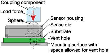
Figure 6: Optimal Alignment of Load Force with Sensor
- 4.2 Root Cause of Coupling Issues
To obtain consistent and precise findings, the sensors must be properly installed with the spheres correctly aligned. The sphere uses a contact point to transfer the load. If the contact point is erratic or not perpendicular, the sphere rubs or presses against the sensor housing, causing variation in the sensor's output. Installing a mechanical coupling component, such as a pin or bushing, can assist in maintaining this alignment.
We will discuss the application coupling and mounting errors in the following content.
- 4.2.1 Coupling Error
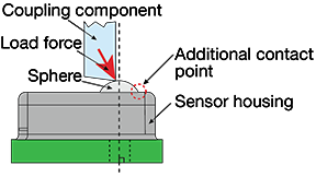
Figure 7: Positioning Error
1. Positioning issues may arise when the coupling component is thin or lacks a smooth surface. There is also the potential for variations in mechanical parts and assemblies to accumulate, resulting in unequal contact point alignment and errors due to load force misalignment. Misalignment can also cause the sphere to press against the sensor housing, creating an extra contact point. Tolerance stackup, an analysis method used to calculate the effects of accumulated variations, can be performed to prevent these types of errors.
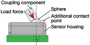
Figure 8: Rotation Error
2. If the coupling component and the sensor are not perpendicularly aligned, rotation errors can arise, causing inaccuracies due to load force misalignment.
3. If the coupling component contacts the sensor housing, sensor readings can be inaccurate due to the load force being distributed between two contact points. With sufficient load forces, the housing can be damaged, leading to losses in sensor accuracy.
- 4.2.2 Mounting Error
1. If the sensor is not properly supported by the mounting surface, inaccuracies can occur. Bending tension from the substrate may transmit unnecessary stress to the sensing die if it does not have the proper support. Some of these inaccuracies may be rectified by sensor auto-zero calibration, a software method where the sensor is recalibrated based on a known reference point.
2. Package stresses, similar to mounting errors, can occur when external forces cause stress on the sensor, skewing the results. These errors can, in some cases, also be rectified by auto-zero calibration.
3. If the vent hole of the sensor is blocked, any air that is trapped within may create excess pressure as the sphere presses down on the sense die. This pressure may cause inaccurate results.
- 4.3 Coupling Mechanism to Provide Proper Load Force
The following are examples of coupling mechanisms that are designed to provide the correct load force to the sensor.
- 4.3.1 Using Leverage
Levers are commonly used to adjust the magnitude and location of the load force. Levers allow the force to act on a flat, level contact surface, optimizing contact against the sensor's coupling sphere. Figure 9 illustrates a force sensor being used with a parallel lever (left) and right angle lever (right).
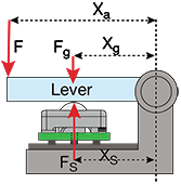
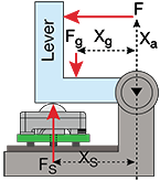
Figure 9: Parallel Lever and Right Angle Lever
The following equation shows the load force transferred to the sensor in the parallel and right angle lever configurations.

Where:
Fs: Reaction force at the sensor
F: Load force exerted on lever from the coupling component
Xa: Perpendicular distance of load force from the rotation axis
Fg: Force exerted by gravity
Xg: Perpendicular distance of center of mass of the lever from the rotation axis
Xs: Perpendicular distance from the contact point of the sensor from the rotation axis
- 4.3.2 Using only Tubing or Tubing with Protective Cover
Some applications, such as those in the medical industry, require force sensors to couple to the outside of tubing.
This example shows how a sensor calculates pressure when pressed against tubing. Figure 10a illustrates the tubing forced against the top of the sensor in a preloaded state. Even though it is empty, the tube will contribute some force to the sensor. The tubing may also touch the sensor housing and the coupling sphere. Although the force from the tubing contributes to the overall output, the sensor can be configured so that the output shift is minimized.
The pressure in the tubing relates to the force output from the sensor with the following equation: Fs=(2πRh)P
Where:
Fs: Force of the sensor
R: Radius of the coupling sphere (1/32")
H: Height of the tubing contact
P: Pressure in the tubing
Another coupling strategy is to install a silicone cover between the sensor and the tubing, as shown in Figure 10b. This protects the sensor from liquids or other environmental factors, and also adds protection from system vibration. Changes to the thickness of the cover may change the surface area that contacts the sphere, resulting in output variation.
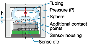
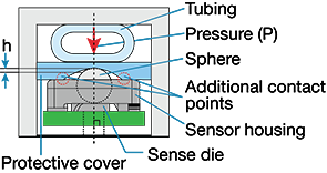
Figure 10: a) Tubing and b) Tubing with Protective Cover
- 4.4 Overforce Design Considerations
Overforce is the absolute maximum force that can be tolerated by the sensor for it to remain within specification once the force returns to the operational force range. Higher forces may permanently disable the sensor. The maximum force tolerated by the sensor, without incurring mechanical damage, is called the burst force.
There are various methods to prevent overforce. Figure 11 illustrates two such methods.
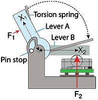
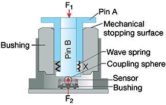
Figure 11: Design Considerations for Preventing Overforce
Figure 11a illustrates the use of a torsion spring connected to two levers, A and B. Lever B is coupled to the force sensor. Force F1 is applied to Lever A, causing the spring to push Lever B down. Lever A has a pin stop, which stops the rotation at the point overforce would occur.
Figure 11b illustrates a linear coupling system using a bushing with two interlocking pins. The interlocking pins are separated by a wave spring. Force F1 pushes pin A until it bottoms out against the bushing, at which point the wave spring is at maximum compression. The fully compressed wave spring should ideally be applying a load slightly larger than the sensor's full-scale span.
- 4.5 Applications
This section will describe example applications using Micro-Force FMA Series sensors.
- 4.5.1 High-End Kitchen Appliance with FMA Series Micro-Force Sensor
FMA Series sensors are used in high-end kitchen appliances and commercial/industrial kitchen equipment such as mixers, kettles, and blenders to provide precise speed control, as well as measurement of ingredients. Figure 12 depicts an industrial blender with 5 micro-force sensors installed. The sensor at position 1 measures the weight of ingredients. Sensors at positions 2 and 3 detect forces from human interaction to control operation of the machine and speed of the blender. The sensor at position 4 detects the presence of a bowl or receptacle, and the sensor at position 5 measures its weight. All sensor data is transferred to the MCU through the I2C bus.

Figure 12: Industrial Blender
- 4.5.2 Robotic Surgery Equipment with FMA Series Micro-Force Sensor
Figure 13 depicts the use of FMA Series sensors in robotic surgery equipment. The micro force sensors provide a sense of touch, helping to mimic the dexterity of human hands and wrists. This tactile force helps to ensure proper instrument grip. The position of the four sensors is represented by the "1" in the figure. The direct mechanical coupling to the sensor provides a more stable and reliable mechanical interface to the application. Sensor data is transmitted through the digital I2C interface. Using the data from the force sensors, the movement of the arms can be made repeatable.

Figure 13: Robotic Surgery Equipment
5. Glossary
- Auto-Zero: A technique for calibrating pressure sensors where a known reference condition is sampled and used for correction of output errors.
- Sensor Calibration: An adjustment or series of adjustments to make sure that the sensor delivers accurate and repeatable results.
- Elastic Modulus: The ratio of stress to strain, where stress = force / cross section area, and strain = change in length / original length. Essentially, the Elastic Modulus gives an idea of the stiffness of the material.
- Linearity Error: The maximum deviation of the sensor output curve from a specified straight line over the desired range. One method of computing linearity error is least squares, which mathematically provides a best fit straight line (B.F.S.L.) to the data points.
- Hysteresis Error: The maximum difference in output between two measurements taken at the same point, where the first is taken when increasing measurement values, and the second taken when decreasing measurement values. For example, for force sensors, the first measurement is taken as force ramps up, and the second measurement is taken when force ramps back down.
- MEMS (microelectromechanical systems): A type of device that uses very small components (between 1 and 100 µm) to create electrical and mechanical functionality.
- NEMS (nanoelectromechanical systems): A type of device that uses components on the nanoscale (1-100nm) to implement electrical and mechanical functionality.
- Null Offset: The output of the sensor when the pressure or force on both sides of the diaphragm are equal.
- Null Temperature Shift: The change in null resulting from a temperature change. A null shift is not a predictable error, because it can shift up or down from unit to unit. Change in temperature causes the entire output curve to shift up or down along the voltage axis.
- Repeatability Error: The maximum deviation in output readings for successive applications of any given input force with other conditions remaining constant.
- Ratiometricity: The state where the zero point and sensitivity are proportional to supply voltage, with other conditions remaining constant. For example, if the supply voltage fluctuates, the output also fluctuates.
- Sensitivity Temperature Shift: The change in sensitivity due to a temperature change. In many sensors, a change in the slope of the sensor output curve can be caused by changes in temperature.
*Trademark. Honeywell is a trademark of Honeywell Inc. Other logos, product and/or company names may be trademarks of their respective owners.
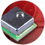
- Compensated/amplified, mechanically-coupled sphere contact element
- Sensor short and open diagnostics
- 20% to 80% transfer function
- 3.3V ±10% supply voltage
- Low power consumption of 14mW
For more force sensors products Shop Now
Test Your Knowledge
Sensors VII
Are you ready to demonstrate your force sensors knowledge? Then take this 10-question quiz. To earn the Sensors VII Badge, read through the module, attain 100% in the quiz, and leave us some feedback in the comments section.

