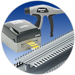
Control panels house the control circuits, power supply, and interconnects required in a process and automation control system. A good control panel design is required to ensure reliable functioning and maintenance of the system over the lifecycle of the installation. It must be designed in accordance with safety requirements and regulatory standards. In this learning module, we will cover the best practices to follow when designing a control panel.
Related Components | Test Your Knowledge
2. Objectives
Upon completion of this module, you will be able to understand:
- Industrial control panel design
- Space optimization techniques
- Power distribution technology
- Noise mitigation techniques
- Data cabling
- Automation in a control panel
- Security in a control panel
3. Designing the Control Panel
A control panel is designed for a specific equipment arrangement and includes devices that allow an operator to control specified equipment. They are made in different shapes, sizes, and customized to individual requirements. Whether the control is manual or automated, equipment and operator safety is of the utmost importance. A thorough understanding of the operation or process and the electrical, electronic, and mechanical devices is required.
- 3.1 Design Process
Industrial control panel design starts with identifying design requirements. The design includes planning by defining the following points:
- Sequence of Operation: The sequence must list each operational step. An application may be better suited for using a flowchart that shows the sequence of operational via decision-making steps and actions that need to take place.
- Schematic: This includes a schematic or flow diagram combining all the equipment and devices used in the panel. The flow uses a high-voltage to low-voltage and input-to-output design layout. In standard practice, the input device is placed on the left-hand side of drawings and output devices on the right-hand side.
- Panel Layout: You should pay attention to component location and spacing in a panel. We need to follow the reference code for mounting distances and clearances. The higher voltage devices must be placed toward the top of the panel, keeping maximum possible distance between the high-voltage devices and any electronic devices, such as PLCs, DC power supplies, and electronic timers. Keeping the high-voltage devices toward the top allows us to cover all the high-voltage devices with a non-conductive safety shield, whereas keeping lower voltage devices grouped together allows access to control wiring.
- Wiring Diagrams: A wiring diagram is used mainly for installation by the electrician for routing and terminating the wiring between the various devices in the control system.
- Bill of Materials: The Bill of Materials (BOM) must list each component, the quantity of each component, its part number, a description of the component, and any designations or "marks" that allow us to identify the component on our schematic quickly.
- Software Tools: Documenting our design can be accomplished with software tools such as Autodesk's AutoCAD
or AutoCAD LT
software.
- 3.2 Safety
Another critical aspect to be considered before designing an automated control system is safety. The following are a few safety points to be considered:
- Eliminate the risk of electrical shock and fire
- Safeguard operator and maintenance personnel
- Install an emergency stop (e-stop) circuit
- Avoid accidental powering of outputs
- Have an orderly shutdown process
- Possess proper earth grounding
- Have a closed loop control
- Implement finger-safe dead fronts
- Avoid unauthorized access
- 3.3 Regulations
The design process should meet all applicable regulatory standards and safety requirements. Regulation standards used for design, manufacturing, and installation of industrial control panels include:
- NEC: The National Electrical Code (NEC) is a widely accepted standard in the United States for the safe installation of wiring and electrical equipment. As per NEC 409 standard, industrial control panels operate on 600 volts or less. It also defines Short Circuit Current Rating (SCCR), which delineates the short-circuit current limit that the industrial control panels can safely withstand without shock hazard or fire. Exceeding the SCCR limit can cause enclosure and component failure.
- NFPA 79: NFPA (National Fire Protection Association) 79 is a part of the NEC that refers to wiring standards for industrial equipment. This standard includes electronic and electrical elements of all machinery that works at or below 600V and provides protection from fire and electrical hazards.
- UL 60947-4-1: The UL 60947-4-1 standard defines coordination between the motor starter and the branch circuit protective device. It also provides a technique to measure the performance of these devices if a short circuit happens.
While the above standards are used throughout the world, different countries may follow their own indigenous safety standards. Refer to those standards when appropriate to the country where the control panel will be installed.
4. Space Optimization
Production facility managers have to manage their space efficiently to reduce capital and operational expense. To reduce the enclosure size and footprint of machines, equipment designers and control engineers have to fit more equipment into an existing enclosure.
The following are some solutions to optimize space in the control panel:
- Specify a flexible enclosure
- Full 3D utilization of internal space
- Utilization of corner space
- Use of a modular bus bar system
- Use of a noise shield and shielded duct
- Minimize the external footprint of enclosure
- 4.1 Enclosure Flexibility
The proper selection of a panel enclosure is an essential factor in space optimization. An enclosure is intended to support a variety of accessories that enable component mounting based on the application requirement. The enclosure must support structural members along the sides, top, bottom, and on the doors to minimize overall space. Proprietary product enclosures are available with different mounting rail options such as vertical mounting, horizontal mounting, and full-side mounting.
- 4.2 Utilizing Three Dimensions
The area in the control panel that's difficult-to-use is the space between the enclosure door and the components on rear sub-panel mounting, sometimes referred to as three-dimensional (3D) space. Unique three-piece body enclosures are available that provide easy installation.

Figure 1: Distributed Design Enclosure
Figure 1 shows a distributed enclosure design, which allows the control panel designer to utilize the 3D space and combine both adjustable rack mounted equipment with sub-panel mounted equipment into a 3D space. The hinges connected to the middle section allow the front door to open. Similarly, hinges connected to the rear section allow the middle section to swing open. The separation of a front, middle, and rear section offers easy access to all sections of the panel. The installer can mount the rear portion of the enclosure to a pole or a wall and then mount the sub-panel into the rear section. Next, the installer can mount a middle section to the rear section of the enclosure followed by the front door. To complete the installation, the front door is mounted on the middle section.
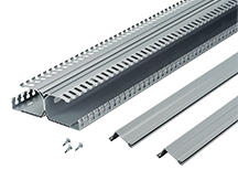
Figure 2: DIN Rail Wiring Duct
The DIN rail is the metal rail used for mounting electrical components, widely used in control panels. Figure 2 shows a DIN rail wiring duct that has two separate wiring channels, which allows a user to mount components in 3D space instead of a sub-panel and saves up to 30% of the space on a sub-panel. It also reduces installation and service time.
- 4.3 Utilization of Corner Space

Figure 3: Corner Space Utilization
In traditional panel layouts, corner spaces are under-utilized. To optimize the control panel space, you can use a Corner Wiring Duct, which fits into corners and provides good wiring transition between rear sub-panels and side sub-panels. Figure 3 shows corner space utilization using a corner wiring duct that can save space up to 12% on sub panels and decrease the enclosure size up to 18%.
- 4.4 Use of a Modular Bus Bar System
A bus bar is a metallic bar used to provide electrical power to each component in the control panel. These can be made of copper, brass, or aluminum, and are available in different shapes and sizes. Modular bus bars provide distributed power throughout an enclosure that can save valuable space while reducing installation time and labor cost. A modular system can achieve higher current and voltage ratings with less copper content compared to a centralized power distribution solution. A 60mm modular bus bar can distribute power up to 1800 amperes and system voltage up to 600 volts. The bus bar system is generally fitted in the sub-panel of the enclosure and supports all control panels. The insulated flat flexible bus bar complements the modular system and can be easily folded and bent into unused spaces.
- 4.5 Noise Shield and Shielded Duct
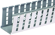
Figure 4A: Shield Wiring Duct

Figure 4B: Noise Shield
The traditional way to mitigate EMI noise across the cables is airspace separation. As per IEEE 518, three to six inches of airspace is required between high voltage to low voltage cables in parallel runs. To optimize the control panel space, we may have to keep wiring closer. Figure 4 shows the Shielded Duct and Noise Shield that can be used to separate noisy drive or motors cables from sensitive control or Ethernet cables. It can reduce EMI noise up to 20dB, which is equivalent to six inches of air spacing and provides additional space saving. The Shielded Duct and Din Rail Wiring Duct together have the potential to save up to 40% sub-panel space.
- 4.6 External Space Saving
Much can be done to optimize the space inside the control panel, but the external footprint minimization is equally important. The control panel must be flexible enough to be mounted on a pole, wall, or floor. Many applications require an air-conditioner or other cooling devices to maintain the temperature inside the panel. You can reduce space by using a thermoelectric cooler, which does not require refrigerant and filters.
5. Power
Control panels use power components that control the flow of electrical power to loads such as Pump Motors, Heaters, and Blow Motors. The following are some types of power components:
- Transformers: They have primary and secondary windings, resulting in power transfer without changing the frequency of the current.
- Circuit Breakers: These are automatically operated power switches, which open the circuit after detecting overload or short circuit conditions.
- Fused Disconnects: These are a combination of a fuse and a manually operated power switch. A fuse opens the power flow when short circuits or overloads occur.
- Contactors: These are electrically controlled switches that work as a relay circuit for high current rating devices. They make or break the power supply to the load(s).
- Operator Switches: These are used to control the starting and stopping of the machine connected to the ICPs.
- Overcurrent Protection Devices: These are used to protect the machines from overcurrent conditions using circuit breakers and fuse circuits.
In any control panel, you should place component groups in a logical manner by function. Most control panels have an incoming "mains" power disconnect switch, commonly located in the upper right of the panel, so it makes both functional and logical sense to locate the devices with the high voltage rating at the top of the panel. From there, the power distribution goes down the panel to the low-voltage power components (most commonly 24VDC) and follows a top-bottom and left-right hierarchy. Every group of power distribution modules must start with a main breaker at the left followed by distribution breakers, fuses, and terminals. This hierarchy reduces troubleshooting time and keeps power distribution functionally sound and consistent.
The control panel includes power distribution units used distribute power to various locations in the panel as per the application requirement. There are two types of power distribution units:
- Centralized: These power distribution units distribute power from a central power source to each component in the panel. Centralized systems are bulky and require more power, cable routing, and thermal management components such as cooling fans and heat sinks.
- De-centralized: In these units, the system power requirements are divided into multiple power distribution centers spread throughout the panel. They provide customization and standardization of power distribution centers for each subsystem. Changes in the system do not need a redesign of the complete power supply system, but only require a change in a specific section that needs modification.
A control panel requires an uninterrupted power supply to provide continuous availability in the automation process. Power line glitches can cause downtime for small intervals. An Uninterruptible Power Supply (UPS) can provide power backup when regular power sources fail, or voltage drops (i.e., brownouts) to an unacceptable level. An ordinary UPS relies on batteries; if the batteries fail, the downtime goes up. Ultracapacitors are high-density storage devices with a capacitance up to 10,000 times greater than conventional capacitors. An ultracapacitor-based UPS provides an alternative source of DC power to traditional rechargeable batteries. The design and size of the UPS depend on power backup requirements.
Fault currents caused by lightning or high voltage spikes can flow through unintended paths (including humans), causing damage to the equipment and human life in the vicinity of the equipment. An arc flash is a sudden release of energy through the air from one voltage phase to another, or one voltage phase to the neutral line. The rise in temperature and pressure can cause an arc blast, leading potentially to fire and damage to the life of an operator and equipment. To address fire and explosion hazards caused by arc flash in electrical equipment, control panels are designed and constructed in accordance to the the (US) National Fire Protection Association's Standard for Electrical Safety in the Workplace (NFPA70E).
A good grounding system provides a path for unwanted currents to flow into the earth, and protects equipment from damage, improving the reliability of the system. A Structured Universal Grounding Bar System provides multiple locations or ports to terminate different equipment ground conductors to the central panel ground conductor. It provides multiple termination methods and mounting options, making it perfect for any control panel or enclosure application. Every control panel has a Short Circuit Current Rating (SCCR) rating, which is the maximum short circuit current a component or equipment can safely withstand when protected by an overcurrent protective device. The maximum SCCR of an industrial control panel must always be equal to or greater than the Fault Current available from the electrical feeders from which it draws power. Otherwise, a catastrophic and violent equipment component and enclosure failure can occur during a short circuit event.
6. Noise Mitigation Techniques
Electromagnetic Interference (EMI) or "noise" from the electronic components within a panel and the external environment is one of the causes of control system failures. Figure 5 shows the risk to industrial automation systems due to EMI noise.
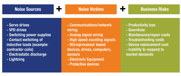
Figure 5: Effect of Noise and Business Risk
The EMI risks increase as we reduce the footprint of the control panel and pack more power devices and network components into a finite space. The control panel enclosure plays a vital role in controlling EMI; it uses the Faraday cage phenomenon and controls the egress and ingress of EMI to and from control panel devices. The ideal Faraday cage is always conductive around the internal devices and acts as an EMI barrier to protect the internal circuitry from outside EMI sources. However, the enclosure must allow access to inside equipment through doors and cable entry points to eliminate "leaks" and allow unwanted EMI to pass-through. Selecting enclosures with proper EMI provisions can mitigate leakage. Adequate electromagnetic compatibility (EMC) shielding around control panel entrance points is needed, as well as the proper selection of enclosure material, as these can mitigate EMI/RFI issues.
Best practices to provide EMI protection include separation of wiring pathways and use of adequate grounding. Others include:
- Grounding incoming circuits to a ground bar
- Using galvanized sub-panels, employing a central ground plane
- Grounding pathways at shielding exit
- Physical separation of sensitive wiring from EMI-generating circuits
- Utilization of wire duct color to communicate clean and noisy pathways
- Use of suppressors and filters, especially after source identification
- Use of shield barriers, to keep EMI inside or outside depending on the design
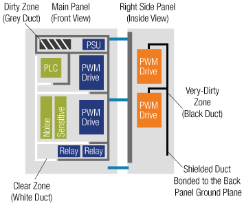
Figure 6: Circuit Layout Separation in Control Panel
Figure 6 shows the reference layout specific to the circuit separation in control panels for noise mitigation. Typically, the victims of EMI are placed on the left side, whereas sources of EMI are placed on the right side of the enclosure. For visual identification of EMI sources and victims, white, black and gray wiring ducts are installed. Using these methods combined or separately can provide a low impedance path to ground, which reduces radiation of EMI and RFI.
7. Data Cabling
Copper or fiber optic data cabling is used to transfer data between various hardware devices. To keep the cable installation neat and clean inside and outside the control panel, we have to run these cables through walls and ceiling panels. The equipment needed to run data cabling throughout a control panel includes:
Wiring Duct: A wiring duct is a wire management solution for routing, protecting, and concealing wiring in electrical control panels. There are many types of wiring ducts. Three common types are:
- Corner Wiring Duct: These are used in fitting wires into the vertical corner of enclosures, providing subpanel space. Panel designers can achieve up to a 20% reduction in the enclosure space.
- Type H Hinged Cover Wiring Duct: The hinged design allows appropriate access to wires and makes modifications possible.
- Type NNC Halogen-Free Wiring Duct: These provide increased heat resistance for outdoor or high-temperature environments and improved safety in the event of a fire. These are non-toxic and lead-free.
Cable Ties: Cable ties are used to clip, clamp, bundle, and manage wire.
Cable Accessories: Assist in routing and securing control panel wiring quickly. Cable accessories provide design flexibility, conserve space, and speed up installation.
Labeling: Printed information about specifications, identification, and safety signs have to be marked or labeled on cables, terminal blocks, safety signs, and pipes. Handheld Thermal Transfer Desktop and Portable Printers enable fast, high-quality label production for control panel identification. A Hand-Held Thermal Transfer Printer with label cut-to-length functionality eliminates label waste and label trimming labor. The fast-loading label holders contain a cohesive memory device for automatic formatting, recall the last legend used, and the count of labels remaining in the holder.
Terminals, Disconnects, Splices, and Ferrules: These are types of connectors that are used with wires and cables to either join them together or connect to a component. They provide consistent and reliable terminations.
Industrial Net Connectors: These offer panel designers a reliable network-cabling infrastructure. They include enclosures designed to withstand the harsh conditions of factory environments. An industrial Ethernet channel solution consists of an IP-protected Ethernet Enclosure and Connectors for protection from dust, short-term immersion in water, and environments of remote industrial facilities.
8. Automation
Electrical control components play a vital role in automation. A control panel includes control devices, which control the sequence of logic operation. Types of control components include:
Control Relays: These are electrical control devices that have a coil, which is energized or de-energized by an electrical voltage. These devices drive high power devices and loads.
Timing Relays: These are a type of control relay with a built-in timer to switch the device on and off at a specific time. There are three main types of timing relays:
- On Timer—When energized, contacts switch to the on-state after an on-delay.
- Off Timer—When de-energized, contacts switch to the off-state after an off-delay.
- One Shot Timer—When energized, it switches to the on-state after a preset time for one event.
- Repeat Cycle Timer—When energized, contacts change the state (on/off) periodically at a preset time.
Programmable Logic Controllers: A PLC is a digital computer, adapted for control of processes, or actions requiring (1) high-reliability control, (2) the ability to program the controller to control sequences, and (3) fault diagnosis. The components in the PLC system are CPU, Memory, Input/Output, a Power supply unit, and programming device.
- CPU—performs functions such as logic operations, arithmetic operations, computer interface, and many more.
- Memory—The CPU uses fixed data. ROM stores the data for the operating system (OS). RAM stores the data values of timers, counters, and status of I/O components.
- I/P section—Input tracks the field devices, which include switches and sensors.
- O/P Section—Output controls other devices, which include motors, pumps, lights, and solenoids.
- Power Supply—The power supply for a Programmable Logic Controller (PLC) converts the input source power into voltages required to power the PLC and its components. In some cases, it also provides an isolated VDC supply to power DC input circuits, switches, and other indicators.
- System Buses—These are a medium by which the digital signals flow in the PLC.
Motor: The control panel provides DC or AC (single-phase or three-phase) power to the motor drive depending on the motor used. AC motor drives convert the fixed frequency to variable frequency, whereas the DC motor drives convert the fixed voltage to variable voltage to drive the motor at different speeds.
Some motor control components that can be part of an enclosure are:
Motor Starters: These are a combination of Circuit Breaker, Contactor, and Overload Relay used for motor and power control. A Motor frequently requires large amounts of power when quickly accelerating (start-up torque). Variable frequency drives and soft starters can be used to limit torque and reduce inrush currents. These features help to extend the motor life and protect the equipment by reducing heating of the motor caused by frequent starts and stops.
- Variable Frequency Drive (VFD): These are advanced solid-state power controllers. The VFD controls the motor speed by varying the voltage and frequency supplied to the electric motor.
- Soft Starters: These are solid-state motor power controllers. Instead of opening and closing a power circuit, they vary the motor input voltage. They provide smooth on-off transitions, which reduce mechanical and electrical shocks associated with starting and stopping a motor.
9. Security
It is necessary to integrate security into a control panel enclosure to not only protect data streams from data loss, network failure, and cyber-attack, but also to protect panel enclosures from unauthorized access.
To secure Confidential or Mission-critical information on the storage environment requires varying degrees of protection or access layers. A physical security-layered approach can mitigate the expense of stolen information and the cost of damage from unintentional access by controlling equipment access and network security.
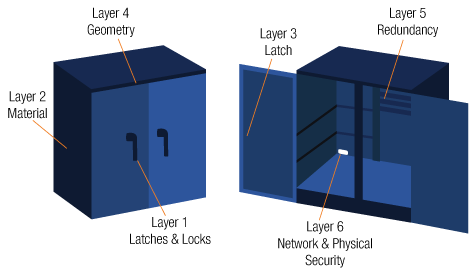
Figure 7: A six-layer security enclosure
Layer 1: The first layer is the locks and latches that secure the physical entry into the enclosure. An enclosure without external locks or unprotected hinges can be a target for tampering. Placing flush mount locks and hinges inside the enclosure can solve this problem.
Enclosure manufacturers sometimes provide a single master key to access multiple enclosures. This method is not very secure, as a person with knowledge of the lock type can use the generic key to open many enclosures. Physical keys are subject to theft and misuse; digital locks can be fixed inside the enclosure to make them more secure. A combination lock uses a password that is entered on a keyboard in the enclosure to actuate a lever inside and open the enclosure. In advanced systems, Biometric sensors like fingerprint, hand, and eye scanners use recognition software to detect an authorized user before granting access.
Layer 2: The second layer represents the material used for enclosure construction. Metallic enclosures are typically made of aluminum or steel. The toughness of stainless steel makes an enclosure very secure, with little concern for accidental damage. Aluminum enclosures are flexible, and therefore easy for fabricating multiple security options within the enclosure. They are less prone to rust and often used in wastewater treatment facilities, telecommunication cabinets, and traffic control equipment. Fiberglass, Polycarbonate, and Polyester enclosures can provide the same level of security with a proper lock mechanism.
Layer 3: The third layer represents the latch type used by the lock mechanism within the enclosure body. Single point or multi-point latch systems are used to keep the door closed. Single latch provides an excellent barrier for small and compact enclosures, while larger enclosures use a multipoint latch mechanism to enhance security.
Layer 4: The fourth layer includes the pry points and enclosure design geometry, which can be used to force open a locked enclosure. By reducing gaps, hiding hinges, and flush mounting the doors, we can eliminate the pry points. Hidden hinges can be designed to open from inside the door.
Layer 5: The fifth layer of security includes an enclosure within an enclosure (redundancy) to prevent entry into specific sections of the enclosure. For instance, we can add security clearance for the power circuit section or the controller section by designing one more lock inside the enclosure.
Layer 6: The final layer includes the safety of network infrastructure cables and connections using locking and block-out devices.
- Lock-in Device and Clips: These avoid the unauthorized removal of wires, connections, cables, patch cords, or other networking devices from the hub. Lock-in devices require special tools for installation and removal of lock-in plugs from the jack. Therefore, these reduce downtime caused by the unintentional removal of cables.
- Block-out devices: These protect the network by preventing direct access to data or connectors/jacks through a physical obstacle that restricts the entrance.
*Trademark. Panduit is a trademark of Panduit Corp. Other logos, product and/or company names may be trademarks of their respective owners.
For more automation products here Shop Now
Test Your Knowledge
Automation I
Are you ready to demonstrate your knowledge about control panel design? Then take a quick 15-question multiple choice quiz to see how much you've learned from this module.
To earn the Essentials Automation 1 Badge, read through the learning module and attain 100% in the quiz.




Top Comments