element14 Community
element14 Community
    Register Log In
  • Site
  • Search
  • Log In Register
  • Community Hub
    Community Hub
    • What's New on element14
    • Feedback and Support
    • Benefits of Membership
    • Personal Blogs
    • Members Area
    • Achievement Levels
  • Learn
    Learn
    • Ask an Expert
    • eBooks
    • element14 presents
    • Learning Center
    • Tech Spotlight
    • STEM Academy
    • Webinars, Training and Events
    • Learning Groups
  • Technologies
    Technologies
    • 3D Printing
    • FPGA
    • Industrial Automation
    • Internet of Things
    • Power & Energy
    • Sensors
    • Technology Groups
  • Challenges & Projects
    Challenges & Projects
    • Design Challenges
    • element14 presents Projects
    • Project14
    • Arduino Projects
    • Raspberry Pi Projects
    • Project Groups
  • Products
    Products
    • Arduino
    • Avnet Boards Community
    • Dev Tools
    • Manufacturers
    • Multicomp Pro
    • Product Groups
    • Raspberry Pi
    • RoadTests & Reviews
  • Store
    Store
    • Visit Your Store
    • Choose another store...
      • Europe
      •  Austria (German)
      •  Belgium (Dutch, French)
      •  Bulgaria (Bulgarian)
      •  Czech Republic (Czech)
      •  Denmark (Danish)
      •  Estonia (Estonian)
      •  Finland (Finnish)
      •  France (French)
      •  Germany (German)
      •  Hungary (Hungarian)
      •  Ireland
      •  Israel
      •  Italy (Italian)
      •  Latvia (Latvian)
      •  
      •  Lithuania (Lithuanian)
      •  Netherlands (Dutch)
      •  Norway (Norwegian)
      •  Poland (Polish)
      •  Portugal (Portuguese)
      •  Romania (Romanian)
      •  Russia (Russian)
      •  Slovakia (Slovak)
      •  Slovenia (Slovenian)
      •  Spain (Spanish)
      •  Sweden (Swedish)
      •  Switzerland(German, French)
      •  Turkey (Turkish)
      •  United Kingdom
      • Asia Pacific
      •  Australia
      •  China
      •  Hong Kong
      •  India
      •  Korea (Korean)
      •  Malaysia
      •  New Zealand
      •  Philippines
      •  Singapore
      •  Taiwan
      •  Thailand (Thai)
      • Americas
      •  Brazil (Portuguese)
      •  Canada
      •  Mexico (Spanish)
      •  United States
      Can't find the country/region you're looking for? Visit our export site or find a local distributor.
  • Translate
  • Profile
  • Settings
Essentials
  • Learn
  • Learning Center
  • Essentials
  • More
  • Cancel
Essentials
Documents Related Components for element14 Essentials: Introduction to RF and End Launch Applications
  • Forum
  • Documents
  • Polls
  • Files
  • Members
  • Mentions
  • Sub-Groups
  • Tags
  • More
  • Cancel
  • New
Essentials requires membership for participation - click to join
Actions
  • Share
  • More
  • Cancel
Engagement
  • Author Author: kabhari
  • Date Created: 1 May 2019 7:18 PM Date Created
  • Last Updated Last Updated: 1 May 2019 8:35 PM
  • Views 1440 views
  • Likes 1 like
  • Comments 0 comments
Related
Recommended

Related Components for element14 Essentials: Introduction to RF and End Launch Applications

element14 Learning Center


image

Introduction to RF and End Launch Applications

Sponsored byimage


The element14 ESSENTIALS of RF and End Launch Applications discusses RF communication fundamentals and some applications of end launch connectors. To extend the knowledge covered in the main module, this supplementary guide discusses the types of related components that can be used for products or prototyping.

Go to Learning Module


image

SMPM Coaxial, Straight Jack, Through Hole Vertical, 50 ohm

Buy NowBuy Now

The SMPM bullet adapter provides the same coveted blind mate functionality as the larger SMP size connectors, mitigating radial and axial misalignment with negligible change to VSWR and other signal losses. The SMPM-series is good for test equipment and racked electronics, where footprint space is a premium and mating boards together is difficult.

image 35% smaller than SMP connectors

image DC, up to 65 GHz

image Bullet adapter provides Blind Mate capabilities

image Available in PC mount, End Launch, and Cabled styles

image Manufactured with high-quality beryllium copper and brass

image Designed to meet MIL-PRF-39012 and MIL-STD-348 specifications


image

SMPM Coaxial, Straight Plug, Solder, 50 ohm

Buy NowBuy Now

The SMPM family includes PC mount and End Launch styles, straight/right-angled, .047 cabled connectors, and sealable flange mounts. All male connectors are offered as a full detent or smooth bore designs for your preference of separation forces.

image DC, up to 65 GHz

image Bullet adapter provides Blind Mate capabilities

image Available in PC mount, End Launch, and Cabled styles

image Manufactured with high-quality beryllium copper and brass

image Designed to meet MIL-PRF-39012 and MIL-STD-348 specifications


image

1.85mm Coaxial, Edge Launch Jack, Solder, 50 ohm, Beryllium Copper

Buy NowBuy Now

The 1.85mm Screw On Board Edge, End Launch Jack is designed for use in a variety of applications while delivering signal integrity in demanding environments. Easy to assemble and disassemble to a PCB, they can be connected with solder or solderless, and adjustable to varying board thicknesses.

image Nickel-plated brass body

image Gold-plated beryllium copper contact

image White PTFE insulator

image Stainless steel bolt and washer

image Impedance: 50 ohm

image Typical VSWR 1.20-1.25

image Maximum frequency: 67 GHz


image

Round Contact, SMA Coaxial, Straight Jack, Board Edge / End Launch, 50 ohm

Buy NowBuy Now

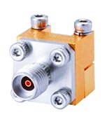
The SMA Self-Fixture End Launch Jack Assembly with round contact attaches directly to a coplanar waveguide circuit board and operates up to 18 GHz with good return loss values. This enhanced end launch connector properly aligns and holds the center contact of a coaxial connector to the circuit board plane without the need for fixtures.

image Gold plated brass body

image Round female (socket) beryllium copper contact with gold plating

image PTFE insulator

image 50 Ohm impedance

image 0-18 GHz frequency range

image Working voltage 335 VRMS max. at sea, level Dielectric withstanding voltage 1000 VRMS min. at sea level


image

145-0701-802 -  End Launch Jack RF / Coaxial Connector, SMK Coaxial, Straight Jack, Screw, 50 ohm, Beryllium Copper

Buy NowBuy Now

The Johnson 2.92mm Connector provides an end launch solution for demanding applications requiring high frequency transmission. Although similar to the SMA interface, a smaller internal body diameter (2.92mm) and air dielectric provide a higher cutoff frequency.

image Performance to 40 GHz.

image Female contacts have a unique three-slot construction, which enhances connectivity by creating a more rugged connector while reducing the chance of intermittent connections.

image Connector mating interface per MIL-STD-348

image The plug connector VSWR is 1.20 Max to 40 GHz and a 12 inch SMK plug to plug cable assembly performs better than 1.35 VSWR to 40 GHz.

image The Field Replaceable Jacks are teamed with a high quality hermetic seal feed thru for use in sealed circuit modules.

image The 2.92mm plug interface employs more precise dimensions than an SMA and uses a shorter snub nose male pin such that the connector bodies align before the contacts engage.


image

SMA Coaxial, Straight Jack, Solder, 50 ohms, Beryllium Copper

Buy NowBuy Now

A straight SMA Coaxial Jack with gold-plated beryllium copper contact. This is used to transition microwave energy from coaxial to planar transmission line structures. This patent-pending connector provides a unique solution for microwave engineers who fabricate circuit designs on fragile high-frequency board substrates. The in-line connector design minimizes reflections as compared to a right-angle (perpendicular) pc mount transition.

image 1.05 + 0.02F (GHz) Maximum at 0 to 18GHz,

image 170VRMS Maximum at sea level, 45VRMS maximum at a 70K.ft working voltage

image 3mΩ (center) and 2mΩ (outer) Maximum contact resistance

image 500-cycle Minimum durability

image 7 to 10-inch.lbs Mating torque

image PTFE insulator


image

SMA Coaxial, Straight Jack, Solder, 50 ohms, Beryllium Copper

Buy NowBuy Now

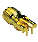
An RF/Coaxial Connector, SMA straight jack receptacle with gold plated brass body; gold-plated contact, printed circuit board style, solder termination type and Surface Mount.

image 50Ω Impedance

image 18GHz Maximum frequency

image 5000MΩ Minimum insulation resistance

image 500-cycle Minimum Durability


image

SMA Coaxial, End Launch Jack, Solder, 50 ohms, Beryllium Copper, .062” Board Thickness

Buy NowBuy Now

This end launch SMA RF Coaxial Connector is attached to the circuit board by inserting the board edge between the legs and soldering the legs and center conductor to pads on the board. For optimum high-frequency performance, the connector to circuit board transition must be adjusted for low VSWR. To compensate for the transition from coax to microstrip, trace widths "A" and "B" must be adjusted based on circuit board thickness. When properly adjusted, this technique yields a low VSWR over a wide bandwidth.

image Gold-plated finish

image Round contact

image 5000MΩ Insulation Resistance

image 500-cycle Minimum Durability


image

SMA Coaxial, End Launch Jack with Thru Hole Terminals, 50 ohms, Beryllium Copper

Buy NowBuy Now

An RF/Coaxial Connector, SMA PC mount jack receptacle with gold plated brass body; gold-plated contact, printed circuit board style, solders termination type, and end launch mount. This high-frequency end launch connector is designed to attach directly to a high-frequency coplanar waveguide (CPW) circuit board transmission line, although other lines such as microstrip can be used with good results. These connectors can be used on high-frequency PC board substrate layers as thin as 10 MIL pin.

image 50Ω Impedance

image 26.5GHz Maximum frequency


image

End Launch, SMA Coaxial, Jack, Solder, 50 ohms, Beryllium Copper, .031” Board Thickness

Buy NowBuy Now

A straight SMA Coaxial Jack with gold-plated beryllium copper contact. It is attached to the circuit board by inserting the board edge between the legs and soldering the legs and center conductor to pads on the board. For optimum high-frequency performance, the connector to circuit board transition must be adjusted for VSWR.

image 335VRMS Working voltage

image 5000MΩ Minimum insulation resistance

image 3mΩ Maximum initial contact resistance

image 7 to 10-inch.lbs Mating torque

image 500-cycle Minimum durability

image PTFE fluorocarbon per ASTM D 1710 and ASTM D 1457 insulators


*Trademark. Cinch Connectivity Solutions is a trademark of Bel Fuse Inc. Other logos, product and/or company names may be trademarks of their respective owners.

  • element14 essentials
  • related components
  • introduction to rf and end launch applications
  • Share
  • History
  • More
  • Cancel
  • Sign in to reply
element14 Community

element14 is the first online community specifically for engineers. Connect with your peers and get expert answers to your questions.

  • Members
  • Learn
  • Technologies
  • Challenges & Projects
  • Products
  • Store
  • About Us
  • Feedback & Support
  • FAQs
  • Terms of Use
  • Privacy Policy
  • Legal and Copyright Notices
  • Sitemap
  • Cookies

An Avnet Company © 2025 Premier Farnell Limited. All Rights Reserved.

Premier Farnell Ltd, registered in England and Wales (no 00876412), registered office: Farnell House, Forge Lane, Leeds LS12 2NE.

ICP 备案号 10220084.

Follow element14

  • X
  • Facebook
  • linkedin
  • YouTube