

 Sensors Series - Part 4 - Medical Sensors
Infectious diseases like the plague, chicken pox, swine flu, and Severe Acute Respiratory Syndrome (SARS) have challenged medical science from time immemorial, and medical equipment used for testing, treatment, and safety is continuously being improved to help save the lives of patients. The infectious Coronavirus disease (COVID-19) is now a global pandemic. As of this writing, one out of six affected patients, per the World Health Organization, needs a ventilator. Thus, there is a massive demand for cost-effective ventilators, as well as other health monitoring systems, laboratory equipment, infusion pumps, and other devices that monitor heart rate and blood pressure. Advanced medical equipment is a must to diagnose patient disorders. Superior sensors and switches that satisfy the requirements of enhanced reliability, product life, accuracy, and sustainability in a demanding environment are a must. In this learning module, we will discuss different types of such sensors, like airflow sensors, thermistor sensing elements, pressure sensors and transducers, humidity sensors, and Hall-effect position sensors, which are all widely used for medical equipment.
Related Components | Test Your Knowledge 
sponsored by
2. Objectives
Upon completion of this module, you will be able to:
- Define the different types of sensors common in medical equipment, such as airflow sensors, temperature sensors, pressure sensors, humidity sensors, and Hall-effect sensors
- Explain the working principles of these sensors
- Understand the importance of sensors in medical equipment
- Discuss applications using these sensors in medical equipment
3. Scope
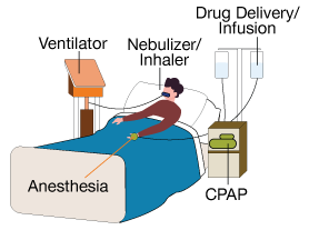
Figure 1: Medical devices ecosystem
A broad range of medical specialty areas and rapidly-progressing sensor technologies offer substantial opportunities for biomedical applications. Medical devices equipped with intelligent and advanced sensors are making human life safer and helping to diagnose patients' problems. Figure 1 shows an ecosystem of medical devices like ventilators, drug delivery systems, and anesthesia delivery systems where sensors have a critical role at every stage of diagnosis. Sensors like temperature sensors, pressure sensors, flow sensors, speed sensors, and humidity sensors are used in intensive care units (ICUs) to monitor air pressure, blood pressure, temperature, and humidity with accuracy and reliability.
One could ask, why does medical equipment need sensors? To answer that question, consider a patient needs a particular quantum of drugs, oxygen, or anesthesia at a specific temperature and humidity condition; any overdose or extra amount may damage the patient's health. Sensors monitor and control all such parameters through their determined functionality. For example, air and oxygen get mixed in a proper ratio inside a ventilator using a flow sensor on a fixed pressure monitored by a pressure sensor and on a specific temperature and humidity observed by temperature and humidity sensors, respectively.
Sensors are widely used in industrial, domestic, and automotive applications. The following module, however, will solely discuss those sensors that are commonly used in the medical field. The scope is limited to temperature sensors, humidity sensors, flow sensors, Hall-effect position sensors, and pressure sensors, along with their characteristics, design considerations, and applications.
4. Basic Concepts
A sensor detects physical parameters like temperature, blood pressure, humidity, or speed and converts them into an electrical signal. This conversion is done by signal conditioning circuitry, via electronics enclosed with the sensor. The complete system, as shown in figure 2, is called a transducer.
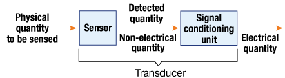
Figure 2: Signal transducer
Different sensors work on different principles. A thermistor and an RTD work on the variation of resistance apropos of temperature. A Hall-effect sensor takes advantage of the Hall-effect principle, which stipulates that when a semiconductor with current flowing in one direction is placed perpendicular to a magnetic field, a voltage is generated at right angles to the current path. A thermocouple works on the principle of the Seebeck effect, in which a temperature difference between two dissimilar electrical conductors or semiconductors produces a voltage difference between the two substances.
We will now discuss the working functions, characteristics, and design considerations of some critical sensors used in medical equipment.
- 4.1 Temperature Sensors
A temperature sensor is a device that senses temperature from a particular source, such as a patient's body, and converts it into an understandable form for that device. Sensing is done via direct contact or remotely with the heating source. A variety of temperature sensors are used today, including thermistors, resistance temperature detectors (RTDs), thermocouples, infrared sensors, and semiconductor sensors.
Thermistors
The term "thermistor" is a combination of "thermal" and "resistor." A thermistor's resistance depends on temperature. These are passive sensing elements, and require additional electronics to generate electrical output, and this output is monitored and used to control the temperature. This bead, cylindrical, or disk-shaped device is fabricated by metal oxides and encapsulated with water-resistant material like epoxy or glass. Thermistors are classified into two types: Positive Temperature Coefficient (PTC) and Negative Temperature Coefficient (NTC). A PTC thermistor increases its resistance with a rise in temperature and decreases with temperature dip. It is generally used as a fuse. The NTC thermistor, by contrast, shows a resistance decrease with a temperature rise and increases with a fall in temperature.
How to Use a Thermistor to Measure Temperature
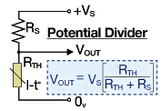
Figure 3: Basic circuit with 192-103LET-A01
A thermistor is a passive device, and an excitation signal triggers its operation for any changes in its resistance. Figure 3 shows a basic divider circuit to measure temperature using a thermistor. A thermistor is a resistive device, and as per Ohm's law, if a current passes through it, there is a voltage drop across it.
When the thermistor resistance changes due to temperature variation, the fraction of the supply voltage across the thermistor also changes, and produces an output voltage proportional to the portion of the total series resistance between the output terminals. This makes it a simple resistance-to-voltage converter. Thermistors are also used with the Wheatstone bridge circuit, a comparator circuit, and an op-amp circuit.
Resistance Temperature Detectors (RTDs)
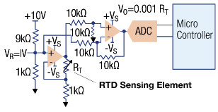
Figure 4: Linear output voltage circuit with RTD sensing element
RTDs are also sensing elements that detect temperature using the principle of metal resistance varying with temperature. They are mostly platinum-based, and need additional circuitry to convert the sensed temperature into electrical signals. Figure 4 shows an RTD element and linear voltage output for signal conversion.
RTDs offer stable and fast linear outputs and have ceramic, plastic, or surface mount housings, including printed circuit board termination. Platinum-based RTDs are laser-trimmed, and thus offer accuracy and flexibility. All these features make RTDs suitable for medical applications.
Thermocouples
A thermocouple is a combination of two metals joined together, forming two junctions. The body, whose temperature is to be measured, is connected with one terminal called the hot junction. The other terminal is connected to a known temperature body, termed the cold or reference junction. The thermocouple thus measures the body's unknown temperature in relation to the known temperature of the other entity. It takes advantage of the Seebeck effect, which states that when two different metals are joined together at two junctions, an electromotive force (emf) is generated at those places. The amount of emf generated is different for different combinations of metals.
Medical applications use thermistors or RTDs to detect temperature. Thermistors employed in medical equipment to monitor patients' temperatures must be sensitive and interchangeable. Thermistors embedded in blood analyzers record motor, chamber, and diffusion lamp temperatures to prevent overheating.
- 4.2 Humidity Sensors
Humidity sensors, also known as hydrometers, are devices that measure the water amount present in the surrounding air. The relative humidity is the ratio of the actual water vapor pressure present in the air at a temperature to the maximum water vapor pressure present in the air at the same temperature. Humidity sensors also measure temperature. Humidity measurement usually refers to relative humidity, unless otherwise defined.
Humidity sensors are classified based on the parameters used to measure humidity, and among these are electrical conductivity humidity sensors, capacitive humidity sensors, and thermal conductivity humidity sensors.
Electrical (Resistive) Conductivity Sensors
Resistive humidity sensors measure resistance (impedance) or electrical conductivity. They work on the principle of conductivity in non–metallic conductors being dependent on their water content. These sensors are usually made from relatively low resistive materials. Their resistivity changes are inversely proportional to humidity changes, and such resistivity variation can be easily measured.
Thermal Conductivity Humidity Sensors
Thermal conductivity humidity sensors are sensors that measure absolute humidity. A thermistor is used as a sensing element. Two tiny thermistors with negative temperature coefficients are used as a bridge circuit. One thermistor is hermetically sealed with dry nitrogen, while the other is exposed to an open environment through small vent holes. When power is switched on, the resistance of both thermistors is calculated, and the difference is directly proportionate to absolute humidity (AH).
Capacitive Humidity Sensors
A simple capacitive RH Sensor can be crafted from an air-filled capacitor, but air cannot be used as a dielectric for practical applications. An appropriate dielectric material (isolator) whose dielectric constant varies with humidity is thus used between the capacitor plates. A hygroscopic polymer film is used as a dielectric depositing two layers of electrodes on either side. These sensors have near-linear output and detect a broad RH range. Both analog and digital capacitive humidity sensors are available.

Figure 5: A typical application circuit for HIH series humidity sensor
Analog type humidity sensors use analog signal conditioning circuitry and generate linear output. The HIH-5030/5031 series sensors are analog and deliver instrumentation-quality RH sensing performance in a solderable SMD. They use laser trimmed, thermoset polymer capacitive sensing elements with on-chip integrated signal conditioning.
Digital humidity sensors are based on the I2C or SPI communication protocol and yield a digital output. Honeywell's HIH8000 series are an example of a digital humidity sensor and offer relative humidity as a digital output. They can interface with other circuitry on I2C. These sensors produce an accuracy level of ±2.0 %RH and a temperature accuracy level of ±0.5 °C. They are stable and reliable, with true temperature-compensated digital I2C or SPI output, energy efficiency, and ultra-small package size and options.
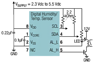
Figure 6A: Application circuit for I2C based sensor
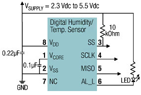
Figure 6B: Application circuit for SPI based sensor
These high accuracy, stability, and ultra-compact size sensors are suitable for medical applications such as incubators, patient monitors, clean rooms, and ventilators to monitor the air for acceptable moisture.
- 4.3 Hall-effect Position Sensors
Hall-effect sensors are electronic devices used to sense position, proximity, speed, and current by measuring a magnetic field. They work on the "Hall-effect" principle. The Hall element is made of a thin sheet of conductive material with output connections perpendicular to the direction of current flow. When this element is subjected to a magnetic field, it generates an output voltage termed Hall Voltage (VH) proportionate to the magnetic field strength. This output voltage is minimal and requires additional electronics to achieve useful voltage levels. When the Hall element is combined with other circuitry, it forms a Hall-effect sensor. So the Hall-effect sensor is an integrated circuit chip containing a Hall element and signal conditioning circuitry.
The Hall-effect sensor output can be analog or digital. The output signal for analog sensors is taken from a transistor, directly connected with the operational amplifier output, as shown in figure 7a. The output voltage is directly proportional to the magnetic field passing through the Hall sensor.
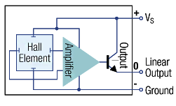
Figure 7a: Simple analog output Hall-effect sensor

7b: Digital output Hall-effect sensor
The digital Hall-effect sensor output is limited to either one of two states: ON or OFF. The output is taken from a Schmitt trigger with integrated hysteresis connected to the op-amp, as shown in figure 7b. When the magnetic flux through the Hall sensor surpasses a set value, the output switches quickly from its "OFF" to its "ON" condition. This built-in hysteresis removes output oscillation as the sensor moves in and out of the magnetic field.
Digital Hall-effect sensors are classified into two basic types: bipolar and unipolar. Bipolar sensors need a positive magnetic field (south pole) to operate them and a negative field (north pole) to release them. In contrast, unipolar sensors need only a single magnetic south pole to operate and release them.
Hall-effect sensors find use as displacement sensors in medical equipment and hospital beds, as well as in force and position sensors fitted into robot-assisted surgery equipment to administer robotic arms that grasp articulated instrument tips.
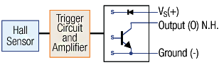
Figure 8: Current sinking output block diagram for SS351AT sensor
The SS351AT, SS451A, and SS551AT sensors from Honeywell are good examples, as they are small, versatile, and operated by the magnetic field from an electromagnet or a permanent magnet. They are designed to respond to either a North pole or a South pole. Figure 8 shows a typical application circuit for a Hall-effect sensor.
Hall-effect magnetic position sensor ICs are designed to provide enhanced output accuracy for smooth motor control. These ICs reduce noise and vibration in a variety of medical applications, including anesthesia machines and motor assembly fan systems. Their small size often enables placement into many compact, automated, lower-cost assemblies. A thermally balanced integrated circuit accurate over a full temperature range is designed to provide proper fan functionality.
- 4.4 Air Flow Sensors
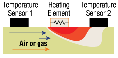
Figure 9: Thermal mass flow sensor
Air flow sensors determine the mass flow rate of air that passes per unit of time. A typical measurement unit for the mass flow of a medium is liters per minute, or LPM. The sensors operate on the heat transfer principle to measure mass airflow, where the difference between a static state with no flow and the heat transfer to a gas or liquid that occurs during flow is measured. A typical airflow sensor consists of a heater element with one or multiple temperature sensors. Figure 9 illustrates a simple thermal mass flow sensor where the "warm" colors represent the heat transfer, which occurs when gas flows from left to right. The hotter zone closer to the heater is indicated by a darker red color, and the cooler farther away is indicated by a yellow color.
These sensors comprise a Microbridge Microelectronic and Microelectromechanical System (MEMS) with temperature-sensitive resistors deposited with attenuated films of silicon nitride and platinum. The MEMS sensing die is positioned in a precisely designed airflow channel to facilitate a repeatable response to the flow.
Airflow sensors are extensively used in medical applications, for example in anesthesia delivery machines, to measure nitrous oxide, air, and oxygen flow. In oxygen concentrators, these sensors detect ultra-low airflow levels when the patient exhales for efficient oxygen delivery. They also find use in sleep apnea machines and gas chromatography. In sleep apnea apparatuses, they monitor a patient's breathing and send the output to reduce airflow when the afflicted individual exhales.
Honeywell's Zephyr HAF Series sensors offer an analog interface for reading airflow over a defined full-scale flow and compensated temperature ranges. These sensors respond swiftly to the flow of gas or air with the help of thermally isolated heater and temperature sensing elements. High accuracy, better reliability, and repeatable measurements make them suitable for medical applications. The combo of a stable substrate and robust housings makes these products durable.
- 4.5 Pressure Sensors
Pressure is a force needed to stop a fluid from expansion, and is expressed in terms of force per unit area. A pressure sensor detects pressure and converts it into a measurable electrical signal, which is proportional to the applied force. Pressure sensors are also known as pressure transducers, piezometers, and pressure transmitters.
A pressure transducer consists of a sensing element that gets deformed with the application of force. The electrical circuitry detects such deformation and converts it into an electrical signal.
A pressure sensor has three principal measurement modes: absolute pressure, differential pressure, and gauge pressure. Different techniques are used to sense these different pressures. A pressure sensor, based on its sensing technology, can be classified as:
- Resistive: these sensors utilize the variation in the strain gauge electrical resistance bonded to the diaphragm open to the pressure medium. These strain gauges frequently include a metal resistive element on an elastic backing deposited directly, utilizing thin-film processes or bonded to the membrane.
Piezoresistive sensors take advantage of semiconductor materials' resistivity changes when subjected to diaphragm deflection strain. The magnitude of difference may surpass 100x the resistance change created in a metal strain gauge. Piezoresistive sensors measure smaller pressure changes as compared to ceramic or metal sensors. Strain gauge elements in a Piezoresistive sensor are made of semiconducting material or metal.
A piezoresistive pressure sensor works on the principle that the conductive material changes electrical resistance when stretched. The strain gauge linked to a diaphragm detects a resistance change upon sensor element deformation. This resistance variation is converted to an output signal. The sensor is used for absolute, gauge, relative, and differential pressure measurement, in both high- and low-pressure applications.
The RSC Series is a piezoresistive silicon pressure sensor providing a reading pressure digital output over the stated complete temperature and pressure span. It is temperature compensated and calibrated for sensor offset, non-linearity, sensitivity, and temperature effects using an integrated EEPROM 24-bit analog-to-digital converter. Pressure data is acquired at rates varying from 20 to 2000 samples per second over the SPI interface. Figure 10 shows a recommended circuit and internal block diagram of this piezoresistive sensor.
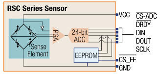
Figure 10: Application circuit and block diagram of the RSC series piezoresistive pressure sensor
- Capacitive: Capacitive pressure sensors measure pressure by detecting electrical capacitance changes caused by diaphragm movement. A capacitor comprises two parallel conducting plates parted by a small gap. The capacitance is described by:

Changing any variable will result in a corresponding change in capacitance. The spacing is easy to control, and it can be done by making one or both plates a diaphragm which gets deflected by pressure changes.
- Piezoelectric: A piezoelectric sensor works on the piezoelectricity principle, a phenomenon where electricity is generated if the material is subjected to mechanical stress. Only a few elements have piezoelectric traits. They are robust and see wide industrial use.
- Optical: Optical pressure sensors detect pressure change via an effect on light. It can be as simple as a mechanical system that blocks light with a rise in pressure. In advanced sensors, the phase difference measurement allows an accurate measure of tiny pressure changes.
- MEMS: Micro-Electro-Mechanical System (MEMS) sensors comprise, at micron-level resolution, a capacitive or piezo pressure-sensing mechanism fabricated on silicon. The co-packaged signal-conditioning electronics transform the small-magnitude MEMS electrical output to an analog or digital signal. These are generally tiny surface-mount devices approximately 2-3mm per side.
Pressure sensors are used in various medical instruments. In dental equipment, they are used for constant water flow to ensure smooth operation and also control the needed pneumatic tools. They are used in blood analyzer pump systems, where they regulate pressure to draw or transport samples and also control the pressure exerted on blood cells to permit only a single cell to get past the detector at any instance.
Honeywell's TruStability and 26PC Series board mount pressure sensors regulate pump system pressure to draw and carry blood samples. High accuracy, contaminant and corrosion resistance, high reliability, long-term stability, and other features make them suitable for medical applications.
5. Analysis
All sensor types discussed in the preceding content find use in medical equipment. They have a vital role in respiratory systems, dialysis machines, insulin pumps, and other medical applications. We will now analyze how such sensors are essential to these systems, and how they are useful in medical applications, with some use cases.
Ventilators
A ventilator is a medical device designed to mix air and oxygen and push this mixture into and out of a patient's lungs. The ventilator helps a person to breathe by enabling mechanical breathing if one is unable to do so. The technology uses sensors to monitor and control pressure, temperature, flow, air humidity, and oxygen. Figure 11 shows a block diagram of a ventilator, indicating the position of different sensors to control flow. Six types of distinct sensors are employed in this system. The numbers 1, 2, 3, 4, 5, and 6 indicate their place.
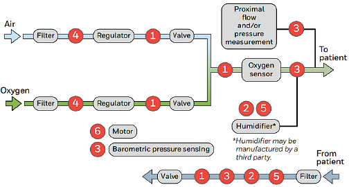
Figure 11: Ventilator Machine
- Airflow sensors: Honeywell Zephyr HAF Series
- Thermistor sensing element: 192 series, 194 series or Packaged temperature probes: 5000 series
- Pressure sensor - board mount: TruStability RSC Series, HSC Series, SSC Series; Basic ABP Series
- Pressure transducers - heavy duty: 19mm Series, MLH Series, SPT Series
- Humidity sensors: Honeywell HumidIcon HIH8000 Series; HIH-5031/5032 Series, HIH-4030/4031 Series; HIH-4020/4021 Series, HIH-4000 Series
- Hall-effect position sensor ICs: SS400 Series, SS360NT, SS360ST, SS460S; SS360PT, SS460P
The system mechanism works like so: air and oxygen first pass through a purification filter while being monitored for fixed pressure by a pressure sensor. This pressure sensor must be of high duty, accurate, and compatible with demanding environments and wet media. It must be easily usable, safe, and stable. The MLC series heavy duty sensors from Honeywell make a good fit for such applications. It is also regulated and mixed.
A flow sensor monitors the flow to mix air and oxygen in the proper ratio. A HAF series flow sensor is suitable due to its high sensitivity, low-pressure drop, and accuracy.
An oxygen sensor monitors the mixed gas to ascertain the quantity of present oxygen, which is again verified for pressure, temperature, and humidity by their respective sensors. The air-oxygen blend is then introduced into the patient's body. It is again taken from the patient and managed for pressure, temperature, humidity, and flow.
Sleep Apnea Machines
Sleep apnea is a severe sleep disorder where breathing comes in fits and starts during sleep. Snoring during sleep and feeling tired even after a full night's sleep are sleep apnea symptoms. The principal types of sleep apnea include the common obstructive sleep apnea, where throat muscles relax. Central sleep apnea, by contrast, is a condition where the brain fails to transmit proper signals to those muscles which control breathing. Complex sleep apnea (aka treatment-emergent central sleep apnea) occurs when someone suffers from both central sleep apnea and obstructive sleep apnea.
If left untreated, sleep apnea may cause cardiovascular disease, high blood pressure, memory loss, and weight problems. The resulting lack of restful sleep may cause job impairment and motor vehicle accidents. A primary treatment option involves Positive Airway Pressure (PAP) machine use. The patient wears a special mask that uses pressure to push airflow through nasal passages, ensuring they don't collapse and stop breathing. A PAP machine uses multi-sensors like temperature sensors, humidity sensors, pressure sensors, airflow sensors, and Hall-effect sensors, as illustrated in figure 12, to control airflow.
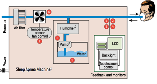
Figure 12: Sleep Apnea Machine
- Airflow sensors: Honeywell Zephyr HAF Series or AWM90000 Series (AWM92100V)
- Humidity sensors: Honeywell HumidIcon HIH8000 Series; HIH-4030/4031 Series, HIH-5031/5032 Series, HIH-4020/4021 Series, HIH-4000 Series
- Pressure sensors - board mount: TruStability RSC Series, HSC Series, SSC Series; Basic ABP Series
- Thermistor sensing element: 192 Series or 194 Series or Packaged temperature probes: 500 Series
- Commercial thermostats: 2450 RC Series
- Hall-effect position sensor ICs: SS400 Series, SS360NT, SS360ST, SS460S
Kidney Dialysis Machines
A dialysis machine cleans a patient's blood by the elimination of unwanted elements and excess water when the kidneys are dysfunctional or suffer from damage. This medical equipment substitutes a few kidney functions by eradicating bloodstream waste via solutes, fluid osmosis, and by diffusion through a semi-permeable dialysis membrane. The membrane has two sides, and each side has a compartment. Blood is pumped into one compartment along the side, and dialysate gets pumped towards the opposite direction on the other side.
Ultrafiltration happens when the hydrostatic pressure is increased by application of negative pressure to the dialyzer's dialysate compartment through the membrane. The consequent pressure gradient forces the dissolved solutes and water to move from blood to dialysate. The now clean blood returns via a circuit to the body.
A dialysis machine uses multiple sensors at different stages for accurate and precise measurement of pressure, flow, temperature, and humidity. Figure 13 shows a block diagram of a kidney dialysis machine with respective sensors and their positions.
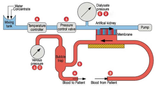
Figure 13: Kidney dialysis machine
- Pressure sensors - board mount: TruStability RSC Series, HSC Series, SSC Series; 26PC Flow-Through Series
- Pressure transducers - heavy duty: 13mm Series, 19mm Series, SPT Series
- Hall-effect position sensor ICs: SS400 Series, SS360NT, SS360ST, SS460S
- Thermistor sensing element: 192 Series or 194 Series
- Force sensors: FSA Series, TBF Series, 1865 Series
6. Glossary
- Zero-Power Resistance (RT): Zero-power resistance is a thermistor's DC resistance value measured at a particular temperature with sufficiently low power dissipated by the thermistor. Any further power decrease will have the consequence of a maximum 0.1% variation in resistance.
- Thermal Time Constant: For a thermistor, this is the time needed to change 63.2% of the total variance between its initial and final body temperature when subjected to any step function change in temperature under zero-power conditions.
- Stability: The stability of any thermistor is the thermistor's ability to retain particular characteristics after being subjected to designated electrical or environmental test conditions.
- Beta (°K) value: This represents a thermistor's material constant and expressed in degrees Kelvin. Beta, unless specified, is derived from thermistor resistance measurements acquired at 0° and 50°C.
Beta Formula used for Thermistors:
- Relative Humidity (RH): This is the ratio of mass (vapor) to mass (saturated vapor) or the ratio of the actual vapor pressure to saturation pressure. The RH is a function of temperature and, thus, is a relative measurement.
- Dew Point: This refers to the temperature at which water vapor present in the gas condenses to water. It is a function of pressure but temperature independent, and is thus an absolute humidity measurement.
- Hall-effect: This refers to the voltage between two edges of a current-carrying conductor. The edge faces are perpendicular to a magnetic field.
- Mass Air Flow: This is a dynamic mass/rate unit measured in grams/minute. If the volumetric flow is referenced to standard temperature and pressure, the calculation of exact mass flow (g/min) can be obtained from the volumetric flow.
- Flow Hysteresis: Refers to the maximum difference between the output readings when an identical flow is consecutively applied, under identical operating conditions, with the flow coming from opposite directions within the mentioned operating flow range.
- Absolute Pressure: The Pressure measured relative to a perfect vacuum or zero pressure reference.
- Auto-Zero: a compensation technique based on sampling output at a known reference condition, within the compensated temperature and compensated pressure range of the product. Typically, a zero pressure reference such as atmospheric pressure is employed to allow the external correction of Offset Error.
- Gauge Pressure: Pressure measured relative to the local ambient (atmospheric/barometric) pressure.
*Trademark. Honeywell is a trademark of Honeywell Inc. Other logos, product and/or company names may be trademarks of their respective owners.

Test Your Knowledge
Sensors IV
Are you ready to demonstrate your Medical Sensors knowledge? Then take this 15-question quiz to see how much you've learned.
To earn the Sensors 4 Badge, read through the learning module, attain 100% on the Quiz, and leave us some feedback in the comments section.
Top Comments