


Optoelectronics I: Optocouplers
Sponsored by

Should a production line halt because of a failure, millions of dollars and countless opportunities may be lost. Two potential causes of breakdowns are electromagnetic interference and high voltage surges. Does your environment require high voltage isolation, enabling a safe interface between high and low voltage circuits? Do you have a need to protect sensitive low-voltage components?
Optocouplers permit electrical circuits and highly diverse voltage levels to work together as a system and interface with each other, while remaining electrically isolated or galvanically separated. This learning module covers the concepts, design, and implementation of optocouplers, a light emitting diode integrated with a photodetector in one package to provide electrical insulation and signal isolation.
2. Objectives
After completing this module, you will be able to:
 Discuss the basic concepts of an optocoupler
Explain how optocouplers work
Understand isolation technologies
Describe the different types of optocouplers
Optocouplers, sometimes referred to as opto-isolators or photo-couplers, are semiconductor devices that isolate unwanted signals by physically separating high-voltage circuits from low-voltage circuits.
Optocouplers are used in an array of isolation applications, ranging from data communications and digital logic interface circuits, to power supply and motor control circuits. They are suitable for use in industrial spaces, automotive markets, renewable energy, and mission critical applications such as military and aerospace. They even have a place in electronic hobbyist projects.
The scope of this learning module covers the fundamental of optocouplers, including their construction, operation, design considerations, and types.
Optocouplers provide physical separation while still transferring signals between high and low voltage circuits using a light source. An LED emits infrared light and a photodetector device detects the light. Assembling these two components into an integrated circuit (IC) package gives us a basic optocoupler.
Before investigating commercially manufactured optocouplers, let's explore what is happening inside an optocoupler IC, by assembling our own home made optocoupler isolation circuit, using discrete components from our electronics parts bins.

Figure 1: How to build your own Optocoupler
Using a piece of heatshrink tubing, physically connect an LED and a photoresistor. Changes in light from the LED circuit will be seen by the photoresistor side of the circuit as changing resistance. The LED side of the circuit is physically isolated from the photoresistor by an air gap, and the signal is then transferred across the gap with light.
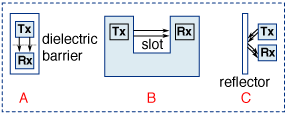
Figure 2: Isolation insulation
Transferring a signal across a physical separation using light is represented in the block diagram A in Figure 2. Tx is the transmitting light source and Rx is the receiver detector. In block diagram B, there is a slot between the LED and the photodetector light sensor. If the slot is blocked with an opaque object, the light transfer is inhibited. In this application, the components could be used for end of tape detection or to signal the level of a liquid. In block diagram C, the components are in a reflective configuration. Light from the source is reflected onto the light sensor. This arrangement could be employed to determine tape-position, shaft rotation, or to detect the amount of smoke in the air.
A commercial optocoupler consists of an infrared emitting diode and a photodetector separated by an optically transparent, electrically insulating film or dielectric. When a current flows through the diode, light is emitted, which passes through the dielectric and is coupled to the photodetector. The photodetector generates a current that is proportional to the light received. This current can be manipulated by various circuitry to perform specific functions. The major function of an optocoupler is to prevent high voltages or rapidly changing voltages on one side of the circuit from damaging components or distorting transmissions on the other side. This is done by optically passing desired signals, while maintaining electrical isolation between two systems.
Optocouplers provide both electrical insulation and signal isolation. The ability of an optocoupler to protect surrounding circuitry against damage from different voltage levels is determined by its physical construction. The physical construction is also what determines the desired isolation voltage.
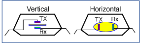
Figure 3: Physical construction
Optocouplers (refer to Figure 3) with a vertical construction have the emitter diode separated from the photodetector in a sandwich configuration. In vertical assemblies, the optics (Tx & Rx) are separated by glass or a transparent polymer dielectric sheet. Breakdown voltages are dependent on the thickness of the dielectric sheet and the specifications of connections with external pins.
In horizontally constructed optocouplers, the emitter diode and the photodetector have a gap between them enclosed in a bubble of silicon. The silicon is designed to trap and reflect the light to the photodetector. Horizontal constructed optocouplers are rated for voltages of < 2.4kV, with vertical devices rated for voltages of > 2.4kv to 6kV.

Figure 4: Basic circuit analysis
The optocoupler isolates the input circuit from the output circuit. This means there can be two separate power supplies, one for the input circuit and one for the output. In this simple circuit, the input is 5VDC and output is Vcc. There is a voltage shift from the input to the value of Vcc. In a circuit where the power supplies for both sides are using the same voltage and current capabilities, the optocoupler is providing isolation without any major shift in voltage or current levels.
In the optocoupler circuit provided in Figure 4, the resistor R1 provides current limiting for the emitter diode (red). Its value is set to limit the maximum forward input current (IF) through the infrared diode in the optocoupler. The values of the forward input current for different types of optocouplers are detailed in their respective data sheets. For the Avago technologies 4N25, the IF is 10ma and for the HCPL-817 it is 50ma. The resistor R2 in the circuit is the load resistor for the photodetector (green). Using the data sheet values, you can calculate the value of R1.
Drop Voltage = Input Voltage - Input Forward Voltage (VF)
R1 = Drop Voltage / Input Forward Current (IF)
HCPL-817 Recommended Operating Conditions
| Parameter | Symbol | Min. | Max. | Units |
|---|---|---|---|---|
| Power Supply Voltage | VCC | 4.5 | 18 | V |
| Forward Input Current (ON) | IF(ON) | 0.5 | 12.0 | mA |
| Forward Input Voltage (OFF) | VF(OFF) | 0 | 0.8 | V |
| Operating Temperature | TA | 0 | 70 | °C |

Figure 5: HCPL-817 graph
The ratio of input current (IF) to output current (IC), called the Current Transfer Ratio (CTR), is expressed as a percentage, and it can be found in the manufacturer’s data sheet. The value of CTR will depend on the type of optocoupler, the value of photodetector collector voltage (VC), and the ambient temperature. The CTR may degrade over time. By starting with an IF that is lower than the maximum, it will extend the device's performance over the intended lifetime of the circuit.
Isolation vs Insulation
In electrical circuits, isolation is required when transmitting signals between high and low voltage systems. The end equipment standards define which level of isolation is needed to ensure safe operation. The threshold of human safety standards requiring reinforced protection starts at 42V DC or 60V AC, and for some sensitive integrated circuits, the voltage level for desired protection may be even lower.
Isolation refers to the separation between two systems or voltage levels, while insulation refers to the actual medium being used to do the separation. For example, an optocoupler is an isolation device with a silicon insulation barrier between the infrared emitter and photodetector.
Circuit designers can encounter three types of isolation-related issues:
Voltage Transients: These are brief and intense surges between two circuits or systems. They are potentially high current or voltage surges that might damage components, causing electric shock that can endanger human life.
Ground Loop Currents: These are unwanted signals between circuits of different ground potentials, which result in ground loops. They are usually found in communication networks having different grounds at various connecting nodes. The potential difference in grounds for an alternating current (AC) or direct current (DC) circuit can generate noise. In order to ensure reliable information exchanges, and to prevent current flow between different ground reference voltages, there is a need to use isolation.
High-Voltage Level Shifting: Using digital ICs results in lower operating voltages. The need for devices to separate sensitive electronics from high power electronics is growing. If the voltage potential is large enough, it can cause damage to equipment, transmission error, or degradation of data signals. Long-term exposure results in the heating and burning of circuit boards, which damages components and causes electric shocks, some potentially deadly to human beings.
For example, in a motor control application the electronic system of a motor consists of 2 stages: the low voltage controller and the power module. Within such a system, it is important to protect and insulate the two stages from switching transients and common mode voltage fluctuations. At the same time, it is necessary to provide level shifting and signal isolation of interface control and feedback circuits.
There are three main levels of insulation, called functional, basic, and reinforced. Functional insulation is needed for correct operation between different potentials in a system. Basic insulation provides protection for users from electrical shock, as long as the insulation barrier remains intact. Reinforced or double insulation provides fail safe operation in that, should one level of insulation fail, a second level will continue to protect the user.
The level of insulation required is very much dependent on the failure mode of a component under fault conditions. Reinforced insulation is only approved for a fail safe component. This means that reinforced insulation not only provides protection from electric shock, it has a failsafe design with a user's accessibility permissible.
In the market today, isolation devices based on optical technology (optocouplers) are mainly still being used. However, alternative isolation devices based on magnetic, capacitive, and Radio Frequency (RF) technologies are available and becoming more prominent.
Electrostatic Discharge
One of the primary causes of component failure in high speed logic circuits is Electrostatic Discharge (ESD). ESD can occur from improper device or board handling, improperly designed interfaces, or some other phenomenon that causes a large voltage spike on a device interface. When devices are damaged by ESD, the affected devices might cease to function, exhibit parameter degradation, or demonstrate high failure rates. The only solution is the replacement of the damaged component.
Optocouplers are excellent devices for protecting against ESD problems, especially in situations where two systems are being linked together in electrically demanding environments. Optocouplers allow for ground isolation, making it possible for systems to remain electrically neutral within themselves, even though they may be floating in an electrically noisy environment. These environments can include motor control, switching power supplies, industrial networks, and medical applications.
Electromagnetic Interference (EMI)
Electromagnetic interference (EMI) can be defined as any electromagnetic disturbance that disrupts, degrades, or otherwise interferes with authorized electronic emissions, limiting the effective performance of electronics and electrical equipment.
It can be induced unintentionally, as a result of spurious emissions, inter-modulation products, atmospheric disturbances (including lightning), extra-terrestrial sources (such as sunspots), or intentionally, as in some forms of electronics warfare.
Radio Frequency Interference (RFI) is a special class of EMI in which radio frequency transmissions result in problems in equipment operation. Radio frequency interference can originate from a wide range of sources, such as mobile phones, power lines, transformers, medical equipment, electro-mechanical switches, and devices that transmit RF energy.
Developers explore two aspects of isolation devices when evaluating their EMI performance: the amount of EMI the device itself generates, and the device's immunity from radiated EMI. The utilization of optical, rather than electronic, pathways gives optocouplers the advantage over other technologies.
Optocouplers provide the highest levels of protection and reliability from EMI in electrical systems. They generate the least EMI and are the most resistant to EMI of all the isolation technologies. Similarly, they are the most resistant to damage or disruption by high-voltage transients.
Optocouplers also have a well-defined safety specification that allows them to receive a reinforced rating for safety in critical applications.
Safety Standards for Isolation
International Safety Standards for devices are published to ensure equipment and products are used at a basic standard level of safety. This ensures safety for both the equipment and the people using it. These standards are focused on public safety in the areas of electrical shocks, mechanical hazards, fire, and electromagnetic interference. At the system and component levels, isolation safety standards vary within equipment applications and geographically.
In the industrial market, the system-level safety standards international standards are IEC 6043 (International Electrotechnical Commission), with UL5084 (Underwriters Laboratories) for the United States and EN 624775 (European Union) for Europe. At the component level for optocouplers, the safety standards are IEC 60747-5-5 for International, UL 1577 for the United States, and EN 60747-5-5 for Europe.
To receive an IEC 60747-5-5 approval, optocoupler components undergo a stringent set of qualification tests that includes environmental, mechanical, isolation, and electrical testing. For future optocoupler standards and maintenance, the IEC will become the de-facto standard worldwide.
The criteria for passing the component is the Partial Discharge (PD) test, with a rigorous upper limit of 5 pC. Insulation, as a resistor to current flow, is an important factor in product safety design.
The fundamental principle of designing for product safety is the separation of circuits that present a danger of electrocution from other circuits, or certain parts of the equipment that a user might come into contact with, or that connect to other equipment. The circuit must be safe, not only during normal usage, but also under fault conditions. Two main levels of insulation with clear distinction of safety are:
Basic Insulation Standards
Since January 2004, the standard certification for optocouplers has been IEC/EN/DIN EN 60747-5-58. Although this standard specifically pertains to optical isolators only, devices using other isolation technologies, such as magnetic or capacitive isolation barriers, have obtained certifications to this optocoupler safety standard. This recognition is limited to Basic Insulation only. This level of insulation might not provide failsafe operation.
Devices that are certified and approved under IEC/EN/DIN EN 60747-5-5 with recognition for Basic Insulation only provide basic protection against electrical shock. They cannot be considered as fail safe. Such devices should not be accessible to a user.
Reinforced Insulation
The level of insulation required is very much dependent on the failure mode of a component under fault conditions. Reinforced Insulation is only approved for a failsafe component. This means that Reinforced Insulation not only provides protection from electric shock, it has a failsafe design and it is acceptable for users to have access.
Reliability of High Voltage Insulation
Optocouplers are often used in environments where high voltages are present. Though many safety standard regulations have been established to provide guidelines to the industry on the application of high voltages, the concern with this insulation is the uncertainty of its reliability, due to poorly understood aging and failure mechanisms under electrical and thermal stress.
Another measure of isolation barrier integrity is the high-voltage life test. This is accomplished by simply applying a high-voltage across the isolation barrier and measuring how long it takes for failure to occur in a high temperature environment. RF isolation devices have fared somewhat better than optocouplers, but still only lasted a few hundred hours.
Applications
Optocouplers are used in industrial communication applications, including industrial input-output systems, sensors and temperature controlling systems, power supplies and regulation systems, electric motor control and drive systems, and instrumentation and medical systems.
They can also be found in Industrial Drives, Industrial Networking, Motor Control, PLC Input/Output Isolation, Power Distribution Systems, Robotics, and Switching Power Supplies designs. Optocouplers were initially proven in the first commercial hybrid electrical vehicle (HEV), the Toyota Prius. Optocouplers are being used in recently released models of HEVs and Electrical vehicles (EVs) from Japan, Korea, China, Europe, and the United States. In addition, more than 40 automotive companies, including car manufacturers and tier one suppliers, are using or evaluating isolation products.
Optocoupler Types
| Optocoupler Types | Functional Diagram | ||||||||||||||||||||||||
|---|---|---|---|---|---|---|---|---|---|---|---|---|---|---|---|---|---|---|---|---|---|---|---|---|---|
|
Darlington Output Optocouplers |
 |
||||||||||||||||||||||||
|
Digital Output Optocouplers |

NOTE: A 0.1-µF bypass capacitor must be connected as close as possible between pins 5 and 8. |
||||||||||||||||||||||||
|
Gate Drive Output Optocouplers |
 |
||||||||||||||||||||||||
|
Linear Optocouplers |
 |
||||||||||||||||||||||||
|
Optically Isolated Amplifiers |
 |
||||||||||||||||||||||||
|
Optocouplers - Miscellaneous |
 |
||||||||||||||||||||||||
|
Transistor Output Optocouplers |
 |
||||||||||||||||||||||||
Galvanic isolation: a design technique that separates electrical circuits to eliminate stray currents. Signals can pass between galvanically isolated circuits, but stray currents, such as differences in ground potential or currents induced by AC power, are blocked. Refers to a design or material technique that guarantees voltage and noise isolation across an insulating barrier.
IEC 604: Industrial international standard for equipment and machinery (http://www.iec.ch).
UL 508: US Industrial standard for machines (http://www.ul.com/).
EN 62477: Safety requirements for power electronic converter systems and equipment (https://www.cenelec.eu).
Basic Insulation: Insulation applied to live parts to provide basic protection against electric shock (http://www.601help.com/Disclaimer/glossary.html)
Reinforced Insulation: Single insulation system applied to live parts, which provides a degree of protection against electric shock equivalent to double insulation under the conditions specified in IEC 60601-1 (http://www.601help.com/Disclaimer/glossary.html).
IEC/EN/DIN EN 60747-5-5: International safety standards (http://www.cenelec.org/).
Failsafe: A mode of system termination that automatically leaves system processes and components in a secure state when a failure occurs or is detected in the system.
*Trademark. Broadcom is a trademark of Broadcom Inc. Other logos, product and/or company names may be trademarks of their respective owners.
Shop our wide range of optocouplers, including darlington output optocouplers, digital dutput optocouplers, gate drive output optocouplers, linear optocouplers, and optically isolated amplifiers.
Test Your KnowledgeBack to Top
Are you ready to demonstrate your Optocouplers knowledge? Then take this 15-question quiz to see how much you've learned. To earn the Optoelectronics I Badge, read through the learning module, attain 100% on the Quiz, leave us some feedback in the comments section, and give the learning module a star rating.
| Octocouplers.pdf |

Top Comments