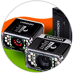
Commercial constraints dictate that the electronics manufacturing and semiconductor industries develop new energy-efficient designs with superior performance at a minimal cost. The sector is burdened with long, drawn-out production processes (for example, semiconductor fabrication takes 100 discrete steps) and wafer-thin margins. Low yields restrain profits due to myriad problems plaguing the internal manufacturing process. Faults, if any, must be detected in their embryonic form. A traceability system must be embedded within the production cycle to observe and verify the work-in-progress at every stage in the manufacturing process.
Related Components | Test Your Knowledge
Data-driven traceability systems scan information-packed codes at every increment and play a crucial role in quality monitoring, production optimization, security, and other internal processes. Key traceability technologies include high-resolution markers for placing tiny barcodes on limited space printed circuit boards (PCBs), components, or enclosures, as well as verifiers along with barcode readers and verifiers optimized for extracting data from such small codes. For engineers, being proficient in traceability technology is a must to ensure a quality, marketable product. In this learning module, we will discuss the key trends and challenges in this area, and examine a few application use cases used in the electronics manufacturing and semiconductor industries.
2. Objectives
Upon completion of this module, you will be able to:
- Define the four phases of traceability
- Explain traceability methodology in the electronics manufacturing and semiconductor industries
- Understand the trends and challenges in traceability
- Discuss example applications using a few traceability systems
3. Scope
Traceability is an umbrella term in the manufacturing and logistics industries. It is a process to map out a product's history, location, and application. You can track and trace every part used in the product, beginning from its manufacture, subsequent assembly, and final release to the customer. Based on unique identifications for who, what, when, and where, you can trace goods throughout the supply and distribution chain. All this information enables easy tracking of faults back to their source (machines, parts, or process) and provides a clear, detailed picture of the problem. Once a cause is identified, it can be effectively and promptly solved. Thus, traceability can also be defined as real-time data collation during the complete production process and the making of records to trace information when needed.

Figure 1: Block diagram of Traceability in the electronics industry
We will now discuss the key trends and challenges that currently shape traceability in the electronics and manufacturing industries, and describe several technological solutions that help manufacturers overcome barriers to success.
- 3.1 Trends
- Analyzing traceability data to determine which machines and processes work
Low operating margins cause semiconductor manufacturers and electronic manufacturing service (EMS) companies to implement real-time traceability systems. A substantial amount of data collected from the system is used to compare, trace the processes, and produce the best quality results. In case of faulty production, you can minimize the number of items that must be recalled by precisely identifying the affected items. If a particular machine consistently produces flawed electronic boards, it is relatively simple to identify that machine by meticulously tracking through the surface-mount technology (SMT) lines that assemble them. Several options exist when it comes to integrating traceability solutions into SMT equipment. Omron's Panel Scan technology allows the production line to capture barcode data from multi-array PCBs in a single step. - Scanning barcodes to follow production "recipes" and enable lights-out manufacturing
Traceability streamlines production by automatically directing the system to route works-in-progress to the appropriate stations. In a sense, it helps the assembly equipment automatically follow production "recipes." This is achieved through the inclusion of specific barcoded steps in the "recipe." The codes run alongside the primary component identification data. Introducing greater automation into digital and semiconductor manufacturing enables companies to take advantage of the current trend toward "dark" or "lights-out" production, which eliminates the human presence and makes for more productive factories, while reining in upkeep costs.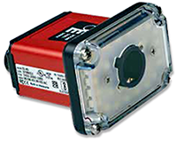
Figure 2: Omron MicroHAWK ID-45 miniscule industrial reader with embedded Ethernet, liquid lens auto-focus and 24-high-intensity LEDs including white, red, blue and optional IR.
A good example is an illumination integrated into barcode scanners that enables imaging systems to locate PCB codes and capture them. Optimal lighting is essential for reading low contrast codes, which is a common bugbear in the digital and semiconductor industry. A lack of real estate makes it impossible to place a big black-and-white code on an item, so EMS manufacturers generally compromise with tiny codes on various backgrounds, including green, red, and blue. To ensure that these small, low-contrast codes can be read, Omron equipped its MicroHAWK ID-45 industrial barcode reader with a 24 LED array.
- Using traceability to streamline testing processes
Printed circuit boards undergo a rigorous testing process. Each board is logged, inspected, and thoroughly tested to ensure near-perfect quality before being released into the market. Different PCBs are tested in different ways, adding complexity. Barcodes indicate the specific tests to be run on a particular PCB. In many manufacturing environments, a tiny, two-dimensional Data Matrix symbol encapsulates this data along with a unique identifier for each board. These symbols inside test adapters indicate which tests are required to ensure that a given PCB is fully functional.
- 3.2 Challenges
- Not knowing where to begin
Implementing a traceability system is a big challenge, since one might be unaware of where to start the process. This is due to the lack of a "big-picture" understanding of traceability. Omron offers the "Mark, Verify, Read, and Communicate" (MVRC) concept to overcome this challenge. This concept gives a sequential phase of traceability, starting with marking information on parts and verifying those marks to be readable, then capturing the data with a scanner, which is then fed back into the manufacturing engineering system (MES) for further analysis. Omron also provides all-in-one solutions that take care of every traceability need. - The transition from a homemade MES to an automated traceability system
Integrating traceability data with homegrown MES may be challenging. The MES must have the correct interface to incorporate the traceability data and extract sense from it. Controllers transfer this data to the MES. Omron offers several of its controllers, such as the NX/NJ series, to handle this information transfer without hampering machine control performance. Another way to facilitate this transition is to implement a seamless, flexible, packaged solution. Omron's traceability technologies make easy integration a priority. - Dealing with space constraints on works-in-progress and within assembly equipment
Space constraint is another roadblock in digital and semiconductor manufacturing to implementing a new traceability system or upgrading the existing one. The equipment on most SMT lines presents a complication to accommodate the addition of barcode scanners and other new technologies. Omron's MicroHAWK industrial compact barcode readers, which can be directly integrated into machines, can sidestep such challenges. These small size readers are mighty, fast, reliable, and enhance flexibility using a liquid lens auto-focus feature. Omron's fiber laser markers mark specific barcodes onto tiny PCBs and even more miniature components with a high resolution capable of braving troublesome factory environments.
4. Basic Concepts
The basic concept behind a traceability system is to record the relevant information about any product or its components using identification technology integrated into complex systems, and use this information to track the history of that product. It implies that the markings in work-in-progress (WIP) parts should withstand the tests of time and harsh environments. There is an MVRC (Mark, Verify, Read, Communicate) concept to simplify the traceability process implemented by Omron, as follows:
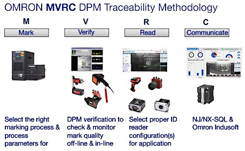
Figure 3: MVRC concept
- M for Mark: The basis for traceability is identifying a part through a mark, and barcodes fulfill this function. A barcode contains all relevant data about a specific part and, when scanned, passes it to a database. It can be considered as the glue adhering the physical world to the digital realm. Markings are inseparable from the objects that carry them, termed as direct part marks (DPMs). Barcodes can be etched, printed, or marked directly on a given part. There are different direct parts marking methods that vary in terms of durability, resolution, and implementation costs.
- V for Verify: It's necessary to verify the printed or etched marks thoroughly to ensure that they start with superior quality, as per ISO standards. Barcode verification is a complex process that grades each code against several essential ISO standards – such as ISO/IEC TR 29158 for direct part marks. A few criteria for grading two-dimensional barcodes are symbol contrast (the intensity difference between light and dark cells), modulation (the degree to which contrast varies throughout the symbol), and print growth (the degree to which one cell type is larger or smaller than the other).
- R for Reading: These barcodes, post verification of WIP parts marks and their codes, must be read at critical points throughout the production process by a barcode reader or imager. This step has multiple benefits. Manufacturing is optimized by code capture and subsequent data analysis, along with problems being identified with particular machines. More code reading implies comprehensive, real-time traceability, and more abundant data to use in optimizing processes.
- C for Communicate: The captured mark or barcode data must be communicated to relevant systems to discover process bottlenecks, determine the source of production failures, and implement targeted recalls. Controllers on the production floor function as data aggregators, collating traceability data and transferring it to the manufacturing execution system. It is vital to have the proper interface for capturing and integrating this information.

Figure 4: The four phases of Traceability
- Traceability 1.0 concerns automatic product identification in manufacturing and industry for accuracy and efficiency when processing a large number of discrete items or transactions. The ability to mark a component and then track it was revolutionary. Barcodes transformed manufacturing and industry, as they improved operator efficiency and productivity. In production, this is frequently the "first step" in implementing traceability solutions.
- Traceability 2.0 concerns inventory management. Now that barcodes were being applied to manufactured items, manufacturers recognized new uses for them. Materials are tracked within the manufacturing facility and throughout the supply chain.
- Traceability 3.0 provides a greater ability to ensure product authenticity and a robust foundation for anti-counterfeiting programs.
- Traceability 4.0 is the combination of the preceding three, along with machine and process parameters to achieve the highest level of manufacturing. This includes Overall Equipment Effectiveness (OEE), production data, and quality data to improve overall manufacturing effectiveness. Omron technology can be used in electronics manufacturing to track a product through all processing steps and develop a Traceability 4.0 solution. Each processing machine writes a proprietary DPM on each product to create a real-time manufacturing genealogy in addition to the machining of the product. Traceability 4.0 systems make automated decisions that optimize equipment and processes based on acquired data, including automatic predictive maintenance. This is facilitated by smart sensors, AI controllers, RFID, and advanced data management software.
How Do Barcode Readers Work?
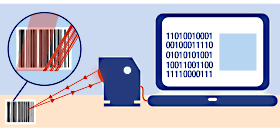
Figure 5: Barcode reader
A barcode is a graphic pattern of black and white parallel lines with a numeric counterpart at the bottom. The workings of a barcode reader can be understood by analyzing the 1D Universal Product Code (UPC) barcode, as shown in figure 5. The width of a UPC barcode is divided into 95 black and white segments. When the light from a barcode reader falls on the barcode, the white portion reflects the light into the photoelectric cell of the reader, whereas the black segments absorb the light and do not reflect it. As a result, photoelectric cells generate a set of off-on pulses, which is again converted to on-off pulses by some electronic means. This pulse stream is stored as binaries in the computer, generating a number corresponding to anything from the product's country of origin to the identity of the product itself.
5. Analysis
Traceability enables electronics manufacturing and semiconductor industries to go for lean manufacturing, assuring quality and the efficient use of resources. We will now analyze the application of traceability in semiconductor and electronic PCB manufacturing industries with some use cases.
Digital Manufacturing Traceability Solution in PCB Manufacturing
Printed Circuit Boards (PCBs) are used in most electronic devices, like TVs, personal computers, phones, or tablets. PCB size has shrunk over time, but PCB productivity has increased through Panelization - the number of PCBs printed on a large panel. These panels pass through various manufacturing process stages to reach final testing. It is essential to record the information for every board and panel at every step to trace problems during the full process. Traceability is implemented by embedding a unique barcode on each panel and each circuit board. Omron designed a traceability solution especially for PCB manufacturing called the PanelScan inspection system, which provides the answer to automating the process of decoding symbols on PCB panels.
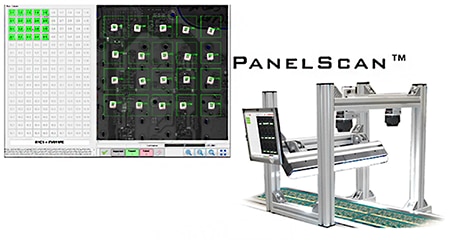
Figure 6: PanelScan
The PanelScan is a user-friendly and easily integrated traceability solution for capturing barcode data. This integrated system replaces error-prone manual scanning with a solution that enables in-motion symbol decoding, and keeps production lines moving. PanelScan captures a complete image of a PCB panel as it passes through the assembly line and decodes all barcodes simultaneously in one click. This system provides features like inline decoding and verification of 1D/2D barcodes, and scalable to Visionscape for additional inspection tasks. It is available in both Standard and Wide versions for flexible implementation. It includes software, camera, lens, light, trigger, and cables.
Next Level Barcode Reading Using MicroHAWK
MicroHAWK series barcode readers and smart cameras provide solutions for traceability, quality control, and vision inspection with a technology that combines advanced optics with monochrome and color image sensors of up to a 5MP resolution and a variety of fixed-focus and autofocus lens options. X-Mode algorithms render damaged and incomplete symbols readable. The technology reliably reads a range of barcodes on different surfaces at high speeds in challenging factory environments. For reliable decoding at the needed rate, barcode readers and cameras come standard with speeds up to 60 Frames Per Second.
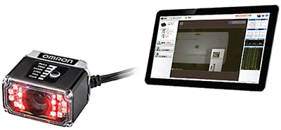
Figure 7: Next level barcode reading using MicroHAWK
The MicroHAWK series offers a wide range of hardware solving barcode reading challenges. For the electronics industry, it provides component and PCB traceability, sub-assembly tracking, automated line changeover, quality assurance, and WIP tracking.
Intuitive and Straightforward to Use
MicroHAWK barcode readers and smart cameras can be easily set up and installed. They can be connected to power and the PC, laptop, or tablet via USB, Ethernet, or serially. You can configure the application. They support a variety of industrial communication protocols such as Ethernet TCP/IP, EtherNet/IP, and PROFINET with onboard I/O, and permit secure integration of data with factory automation applications. The technology used for these devices features:
- X-mode decoding algorithms
- High-speed liquid lens autofocus
- Daisy chain networking
- Onboard configuration database
- Barcode quality monitoring
- Advanced password management
- Rapid Capture mode
- Enhanced integrated lighting
- AutoVISION Machine Vision Software
- Expandable platform with Machine Vision software option
6. Glossary
- Accuracy: This is the determination of whether any element width or inter-character gap width varies by more than the specified tolerance.
- Aspect Ratio: This is a bar code verification term and the ratio of bar code symbol height to symbol length.
- Average Background Reflectance: This is a bar code verification term, and is expressed as a percent.
- Daisy Chain Network: A daisy chain is an interconnection of computer devices, peripherals, or network nodes in series, one after another.
- Data Matrix: This is a two-dimensional matrix barcode in square or rectangle shape, which consists of black and white cells to represent bits. The information to be encoded can be text or numeric data. Each Data Matrix code is unique.
- Depth of Field: This is the distance between the minimum and maximum surface in which a scanner can read bar codes of a specified X dimension.
- Diffuse Reflection: It is the component of reflected light that emanates in all directions from the reflecting surface.
- Liquid Lens: Liquid lens works on an electrowetting process to achieve higher autofocus competences. It is a sealed cell filled with water and oil. The electrowetting process forms the oil drop into an actual lens quickly and accurately. This technology does not involve moving mechanical parts, which makes them highly resistant to shock and vibration. It also enables a stable optical axis in any orientation.
- RFID (Radio Frequency Identification): It uses electromagnetic fields to automatically identify and track tags attached to objects.
- X-dimension: This is the thickness of the narrow bars and spaces in a bar code type, usually measured in mils.
*Trademark. Omron is a trademark of Omron Corp. Other logos, product and/or company names may be trademarks of their respective owners.
For more traceability scanner products Shop Now
Test Your Knowledge
Automation II
Are you ready to demonstrate your traceability in the electronics manufacturing and semiconductors industries knowledge? Then take a quick 15-question multiple choice quiz to see how much you've learned from this module.
To earn the Essentials Automation 2 Badge, read through the learning module and attain 100% in the quiz.




Top Comments