element14 Community
element14 Community
    Register Log In
  • Site
  • Search
  • Log In Register
  • About Us
  • Community Hub
    Community Hub
    • What's New on element14
    • Feedback and Support
    • Benefits of Membership
    • Personal Blogs
    • Members Area
    • Achievement Levels
  • Learn
    Learn
    • Ask an Expert
    • eBooks
    • element14 presents
    • Learning Center
    • Tech Spotlight
    • STEM Academy
    • Webinars, Training and Events
    • Learning Groups
  • Technologies
    Technologies
    • 3D Printing
    • FPGA
    • Industrial Automation
    • Internet of Things
    • Power & Energy
    • Sensors
    • Technology Groups
  • Challenges & Projects
    Challenges & Projects
    • Design Challenges
    • element14 presents Projects
    • Project14
    • Arduino Projects
    • Raspberry Pi Projects
    • Project Groups
  • Products
    Products
    • Arduino
    • Avnet Boards Community
    • Dev Tools
    • Manufacturers
    • Multicomp Pro
    • Product Groups
    • Raspberry Pi
    • RoadTests & Reviews
  • Store
    Store
    • Visit Your Store
    • Choose another store...
      • Europe
      •  Austria (German)
      •  Belgium (Dutch, French)
      •  Bulgaria (Bulgarian)
      •  Czech Republic (Czech)
      •  Denmark (Danish)
      •  Estonia (Estonian)
      •  Finland (Finnish)
      •  France (French)
      •  Germany (German)
      •  Hungary (Hungarian)
      •  Ireland
      •  Israel
      •  Italy (Italian)
      •  Latvia (Latvian)
      •  
      •  Lithuania (Lithuanian)
      •  Netherlands (Dutch)
      •  Norway (Norwegian)
      •  Poland (Polish)
      •  Portugal (Portuguese)
      •  Romania (Romanian)
      •  Russia (Russian)
      •  Slovakia (Slovak)
      •  Slovenia (Slovenian)
      •  Spain (Spanish)
      •  Sweden (Swedish)
      •  Switzerland(German, French)
      •  Turkey (Turkish)
      •  United Kingdom
      • Asia Pacific
      •  Australia
      •  China
      •  Hong Kong
      •  India
      •  Korea (Korean)
      •  Malaysia
      •  New Zealand
      •  Philippines
      •  Singapore
      •  Taiwan
      •  Thailand (Thai)
      • Americas
      •  Brazil (Portuguese)
      •  Canada
      •  Mexico (Spanish)
      •  United States
      Can't find the country/region you're looking for? Visit our export site or find a local distributor.
  • Translate
  • Profile
  • Settings
STEM Academy
  • Learn
  • Learning Center
  • STEM Academy
  • More
  • Cancel
STEM Academy
Blog Raspberry Pi - DS18B20 Temperature Sensor
  • Blog
  • Forum
  • Documents
  • Events
  • Polls
  • Files
  • Members
  • Mentions
  • Sub-Groups
  • Tags
  • More
  • Cancel
  • New
Join STEM Academy to participate - click to join for free!
  • Share
  • More
  • Cancel
Group Actions
  • Group RSS
  • More
  • Cancel
Engagement
  • Author Author: ntewinkel
  • Date Created: 13 Dec 2014 6:22 AM Date Created
  • Views 3105 views
  • Likes 5 likes
  • Comments 8 comments
  • python
  • raspberrypi
  • ds18b20
  • stem space
Related
Recommended

Raspberry Pi - DS18B20 Temperature Sensor

ntewinkel
ntewinkel
13 Dec 2014

Hi all,


In this blog post, I show how to read the temperature from a DS18B20 temperature sensor using Python on the Raspberry Pi.

This sensor is nice not only in that it's inexpensive, but it's also a digital sensor. Given that the Raspberry Pi doesn't easily handle analog inputs, the DS18B20 is a great choice.


In case you need it, here are my previous posts to help you get started with Python programming and IO pins for the Raspberry Pi:

Raspberry Pi - HelloWorld

Raspberry Pi - Blink


For this tutorial, I am using:

1x Raspberry Pi Model B+ running Raspbian (other models should work fine too)

1x breadboard to make the connections

1x DS18B20 temperature sensor - I'm using a waterproof one with a foot long cable containing red, black, and yellow leads

3x M-F jumper wires

1x 10KΩ resistor


Edit: I tried this on a new RaspberryPi and it didn't work. Turns out I missed this step:

- Add the following line to /boot/config.txt

     dtoverlay=w1-gpio

- You can edit that file with the leafpad editor by running "sudo leafpad /boot/config.txt" and then adding that line at the very bottom.

- Save, and reboot.


The hardware connections:

- put the 3 leads of the DS18B20 into the breadboard. (I found this worked ok enough, but ideally it's better to solder some good tips onto them for stronger connections.)

- connect a jumper wire from the yellow (data) wire to pin 7 (GPIO4) on the Raspberry Pi

- connect a jumper wire from the red (power) wire to pin 1 (3.3v) on the Raspberry Pi

- connect a jumper wire from the black (ground) wire to pin 9 (GND) on the Raspberry Pi

- add a 10KΩ resistor between data and power


So that's the hard part.

This is what is looks like:

image

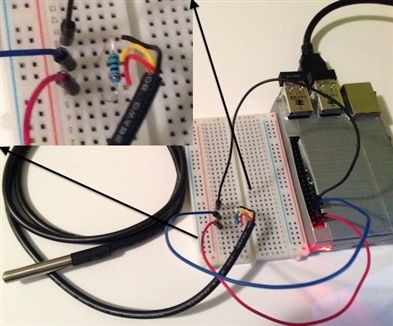
(Check out my duct tape Pi case!)


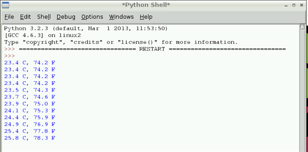
Now open up the attached example (DS18B20.py) and run it, and you should see temperature numbers showing up on the Python console.

If you see error messages, it is most likely due to a loose wire. In my case the DS18B20 leads are a little short and one popped out, which caused some scary looking error messages when I tried to run the script!

The other thing I forgot at first was that 10K resistor - it is vitally important too.


This is what the output should look like, with numbers depending on your temperature, of course. Try putting your fingers on the sensor to see how that affects the readings.

image


For more details, also check out this Adafruit tutorial, which I used as a guide to get started.

The attached Python code is also derived from their example.


Edit: This has been tested and works on both the RPi model B+ and the RPi 2 model B.


Cheers,

-Nico

Attachments:
DS18B20.py.zip
  • Sign in to reply

Top Comments

  • fvan
    fvan over 10 years ago +2
    Well done Nico (and the case is awesome)!
  • mcb1
    mcb1 over 10 years ago +1
    Nice work. I generally use a 4k7, but it seems it can vary down as well. Mark
  • ntewinkel
    ntewinkel over 10 years ago in reply to fvan +1
    Hehe thanks Frederick! I think I need to find some red duct tape to add a the raspberry symbol to it Oh and oops - I see I missed an opportunity to add shameless gratuitous promotion of the duct tape manufacturer…
  • clem57
    clem57 over 10 years ago in reply to mcb1

    Too many 10K ar radio shack LOL

    • Cancel
    • Vote Up +1 Vote Down
    • Sign in to reply
    • More
    • Cancel
  • mcb1
    mcb1 over 10 years ago in reply to ntewinkel

    Is that anywhere in the ballpark of reality?

    Yep perfect reasoning.


    Not sure why Adafruit did either, and I think its the first one I saw.

    There are some proper Application Notes put out by Dallas if you really want to bore yourself. image


    Mark

    • Cancel
    • Vote Up +1 Vote Down
    • Sign in to reply
    • More
    • Cancel
  • ntewinkel
    ntewinkel over 10 years ago in reply to mcb1

    Uhm, yeah... much of that is over my head I think! image


    Cool to see how Pascal used an oscilloscope to figure out what was going on with that!

    Good to know, in case I run into funny business with things not working.


    My understanding is that a too high value resistor would make it difficult for the data line to return to high (3.3v) level (slow rise), and that a too low value would make it difficult for the sensor to make the value low. Is that anywhere in the ballpark of reality?

    I'm guessing it gets really complex when more sensors are added and longer cable lengths are used.


    Oh, and I just checked around a bit - seems most places recommend the 4k7. Not sure why the Adafruit tutorial would include the 10k as an option.


    Cheers,

    -Nico

    • Cancel
    • Vote Up +1 Vote Down
    • Sign in to reply
    • More
    • Cancel
  • mcb1
    mcb1 over 10 years ago in reply to ntewinkel

    Nico

    It's mainly to do with the capacitance/number of sensors v pullup value affecting the rise time of the waveform.

    Some of the documents even show how to use an active pullup.


    Pascal run into the issue with his application, and has detailed it during his posts.

    http://www.element14.com/community/community/design-challenges/forget-me-not/blog/2014/10/25/pas-home-final-summary

    This was the summary but shows it.


    Because the devices and master are open collector, its only the pullup that returns the voltage to the 5/3v3.


    Mark

    • Cancel
    • Vote Up +1 Vote Down
    • Sign in to reply
    • More
    • Cancel
  • ntewinkel
    ntewinkel over 10 years ago in reply to fvan

    Hehe thanks Frederick! I think I need to find some red duct tape to add a the raspberry symbol to it image


    Oh and oops - I see I missed an opportunity to add shameless gratuitous promotion of the duct tape manufacturer in a cheap attempt at bonus points image

    • Cancel
    • Vote Up +1 Vote Down
    • Sign in to reply
    • More
    • Cancel
>
element14 Community

element14 is the first online community specifically for engineers. Connect with your peers and get expert answers to your questions.

  • Members
  • Learn
  • Technologies
  • Challenges & Projects
  • Products
  • Store
  • About Us
  • Feedback & Support
  • FAQs
  • Terms of Use
  • Privacy Policy
  • Legal and Copyright Notices
  • Sitemap
  • Cookies

An Avnet Company © 2025 Premier Farnell Limited. All Rights Reserved.

Premier Farnell Ltd, registered in England and Wales (no 00876412), registered office: Farnell House, Forge Lane, Leeds LS12 2NE.

ICP 备案号 10220084.

Follow element14

  • X
  • Facebook
  • linkedin
  • YouTube