element14 Community
element14 Community
    Register Log In
  • Site
  • Search
  • Log In Register
  • Community Hub
    Community Hub
    • What's New on element14
    • Feedback and Support
    • Benefits of Membership
    • Personal Blogs
    • Members Area
    • Achievement Levels
  • Learn
    Learn
    • Ask an Expert
    • eBooks
    • element14 presents
    • Learning Center
    • Tech Spotlight
    • STEM Academy
    • Webinars, Training and Events
    • Learning Groups
  • Technologies
    Technologies
    • 3D Printing
    • FPGA
    • Industrial Automation
    • Internet of Things
    • Power & Energy
    • Sensors
    • Technology Groups
  • Challenges & Projects
    Challenges & Projects
    • Design Challenges
    • element14 presents Projects
    • Project14
    • Arduino Projects
    • Raspberry Pi Projects
    • Project Groups
  • Products
    Products
    • Arduino
    • Avnet & Tria Boards Community
    • Dev Tools
    • Manufacturers
    • Multicomp Pro
    • Product Groups
    • Raspberry Pi
    • RoadTests & Reviews
  • About Us
  • Store
    Store
    • Visit Your Store
    • Choose another store...
      • Europe
      •  Austria (German)
      •  Belgium (Dutch, French)
      •  Bulgaria (Bulgarian)
      •  Czech Republic (Czech)
      •  Denmark (Danish)
      •  Estonia (Estonian)
      •  Finland (Finnish)
      •  France (French)
      •  Germany (German)
      •  Hungary (Hungarian)
      •  Ireland
      •  Israel
      •  Italy (Italian)
      •  Latvia (Latvian)
      •  
      •  Lithuania (Lithuanian)
      •  Netherlands (Dutch)
      •  Norway (Norwegian)
      •  Poland (Polish)
      •  Portugal (Portuguese)
      •  Romania (Romanian)
      •  Russia (Russian)
      •  Slovakia (Slovak)
      •  Slovenia (Slovenian)
      •  Spain (Spanish)
      •  Sweden (Swedish)
      •  Switzerland(German, French)
      •  Turkey (Turkish)
      •  United Kingdom
      • Asia Pacific
      •  Australia
      •  China
      •  Hong Kong
      •  India
      • Japan
      •  Korea (Korean)
      •  Malaysia
      •  New Zealand
      •  Philippines
      •  Singapore
      •  Taiwan
      •  Thailand (Thai)
      • Vietnam
      • Americas
      •  Brazil (Portuguese)
      •  Canada
      •  Mexico (Spanish)
      •  United States
      Can't find the country/region you're looking for? Visit our export site or find a local distributor.
  • Translate
  • Profile
  • Settings
STEM Projects
  • Learn
  • Learning Center
  • STEM Academy
  • STEM Projects
  • More
  • Cancel
STEM Projects
Blog Book Carrying Robot #6 GPIO Motor control circuit schematics
  • Blog
  • Forum
  • Documents
  • Events
  • Polls
  • Files
  • Members
  • Mentions
  • Sub-Groups
  • Tags
  • More
  • Cancel
  • New
Join STEM Projects to participate - click to join for free!
  • Share
  • More
  • Cancel
Group Actions
  • Group RSS
  • More
  • Cancel
Engagement
  • Author Author: mohanedessam
  • Date Created: 7 Sep 2015 4:55 AM Date Created
  • Views 333 views
  • Likes 1 like
  • Comments 0 comments
  • pwm_controller
  • image_processing
  • teachers_pet_robotics_design_challenge
  • teachers_pet
  • pwm
  • matlab_raspberry_pi
  • raspberry-pi
  • matlab
  • teachers pet robotics design challenge
  • motor_control
  • digital_imaging
  • book_carrying_robot
  • motor
  • simulink
Related
Recommended

Book Carrying Robot #6 GPIO Motor control circuit schematics

mohanedessam
mohanedessam
7 Sep 2015

after  I explained about the software part of my design in my previous post, I would like to describe an important yet very simple interface circuit that I use to control my motors.

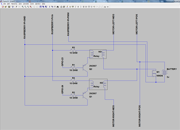
The circuit schematic is shown in this image:


image

the GPIO pins 23 and 24 are connected to the left and right motors in the same way, the GPIO pin is connected to the base of the PNP transistor through a 1000 OHM resistor, the transistor collector is connected to the Raspberry PI digital ground pin, the Raspberry PI 5 volts pin is connected with a 10 OHM resistor to one side of the Relay coil, the other side of the coil is connected to the transistor emitter.

On the motors side, the positive port of the motor is connected to the positive port of the motors battery, the Motor negative port is connected to the Normally-Open (NO) pin of the Relay, finally, the Common (C) pin of the Relay is connected to the negative port of the motors battery.


This circuit is pretty basic and naive, as it doesn't provide speed control of the Motors using the Raspberry PI PWM pin, However, it can be modified to include this feature by using a power transistor with the motors battery. as shown in this image:

image

However, I haven't applied the PWM and speed control part, and it can be considered as an extra feature that can be added later.

  • Sign in to reply
element14 Community

element14 is the first online community specifically for engineers. Connect with your peers and get expert answers to your questions.

  • Members
  • Learn
  • Technologies
  • Challenges & Projects
  • Products
  • Store
  • About Us
  • Feedback & Support
  • FAQs
  • Terms of Use
  • Privacy Policy
  • Legal and Copyright Notices
  • Sitemap
  • Cookies

An Avnet Company © 2025 Premier Farnell Limited. All Rights Reserved.

Premier Farnell Ltd, registered in England and Wales (no 00876412), registered office: Farnell House, Forge Lane, Leeds LS12 2NE.

ICP 备案号 10220084.

Follow element14

  • X
  • Facebook
  • linkedin
  • YouTube