


Teachers Pet ... Robotics Challenge
http://www.element14.com/community/roadTests/1417
| Teachers Pet Challengers | Teacher's Pet Students' Robotics Challenge Finalists |
| Introduction | Teachers Pet Students Robotics Challenge .. Introduction |
| 2nd post | |
| 3rd post | BOE Robot |
| 4th post | Simple Bot Basics |
| previous post | Assemble BOE |
Simple control
In the last post I talked about controlling servos, and the various effects on the BOT movement.
This post is about implementing some of the movements.
The first thing to do is connect the Arduino to the shield.
You then need to connect both servos onto the appropriate place. (The instructions are very clear, so simply follow them)
You'll need to load the Arduino IDE, and connect to the Arduino with the supplied cord.
Depending on your particular Operating System the method changes slightly, but there are plenty of resources on the internet.
Stopped
When you control normal motors, you simply remove the power and the motor stops.
You can get fancy and short the motor, which acts like a brake.
For a servo you need to apply a signal that is halfway between 1300 and 1700 mS pulse width, which is 1500 mS.
( see Continous Servos in BOE Robot )
The servos supplied have an adjustment to zero the motor when you apply a 1500mS pulse width.
I mounted them so the calibration hole was accessible (despite the suggestion that you couldn't)
There is a very good set of instructions and code at Robotics with the Board of Education Shield for Arduino | learn.parallax.com.
In order to adjust the servos to stopped, you load BothServosStayStill from inside the RoboticsBOEShield_Ch2_20120229(1) folder
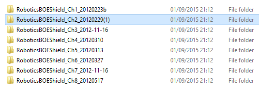
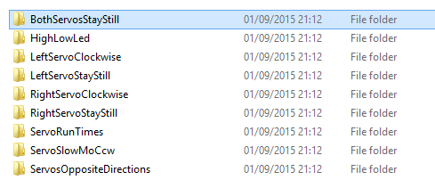
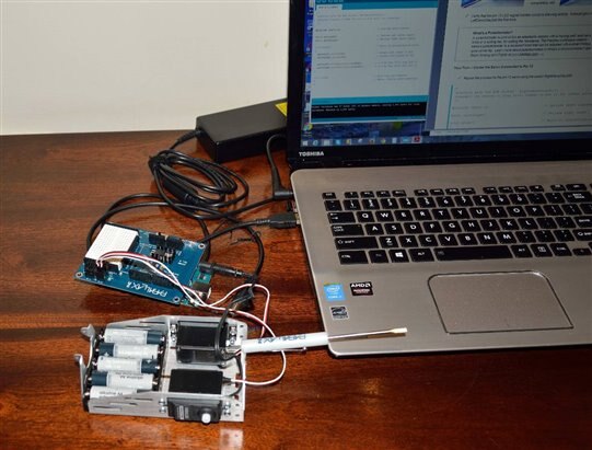
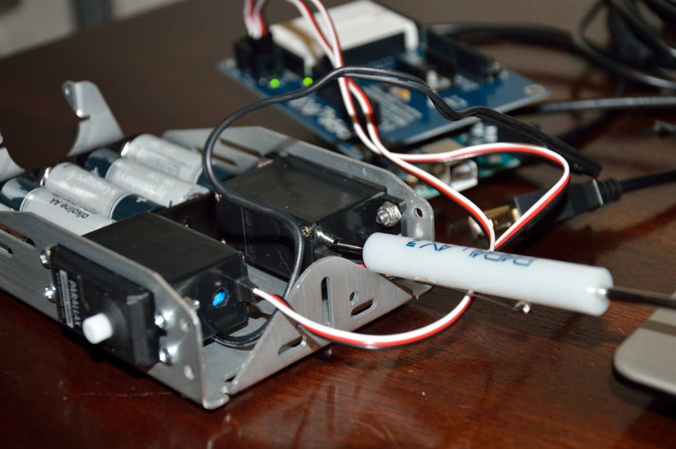
photo source 3 minions (me, myself and I) Adjusting the zero point of the servos.
In my servos they were running slightly, and I inserted the supplied screwdriver and tweaked it until it stopped.
I found it easier to place you finger on the servo shaft and feel when it stopped, and when it started revolving in the other direction.
You simply back it off to get it in the middle of the 'deadband'. ( https://en.wikipedia.org/wiki/Deadband )
Clockwise
The next step is to check they go around and note the speed.
The instruction here Activity 6: Testing the Servos | learn.parallax.com suggests verifying that they rotate at 50-60 rpm.
So how to check for 50-60 rpm?
Good question and without suitable equipment I began ti think of methods that might work.
Method 1 is to count the turns over 1 minute (60 secs).
Method 2 is to time 1, 2 or more turns.
In theory if the servo is turning at 60 rpm, then one revolution takes 1 second.
Considering our reflexes aren't that great, the timing accuracy could make a huge difference, if we try to time it over 1 revolution.
If you time it over 10 revolutions any error is divided by 10, so you get a far more accurate idea of the speed.
Why bother?
Well that is a good question, and I thought about how important it was to know the rpm.
If you want to know the distance, then you need to know the rpm, and then do some maths based on the wheel diameter.
As I discussed in the earlier post ( Simple Bot Basics ), motors seldom run the same speed both directions.
I figure that after setting the BOT to run straight, you could simply run the BOT for 10 seconds and measure how far it travels, set out a measured length and time it.

I tried the various settings, and run the BothServosStayStill in between to check.
Since everything seemed fine, it was time to move to the next step in the instructions.
It's now time to assemble the BOT in order to do the straight line testing.
BUT it's time to pack my bags and head back to NZ, so I'll be packing it up for the trip home.
We have a stopover in Singapore/Malaysia (for work), and with the flights and time change its next Wednesday before I hit NZ.
So until then there won't be any more updates.
Mark