


In my last blog post I outlined how I combined a bunch of autonomous + remote robotic functions into a singular robot!
Functions which could be called were 1. Remote control by arrow keys 2. Light Seeking 3. Touch Sensing 4. Ultrasonic obstacle avoidance 5. Edge Detection and then basically different combinations of each of these accessed by a graphical user interface created in Processing. Observing multiple sensing abilities interact; for example obstacle avoidance, light sensing, and edge detection; was educational for thinking about "machine intelligence" and emergent behavior.
But....what was really missing in my versatile robot was line following and now what was lacking has now been achieved. Here is the explanation:
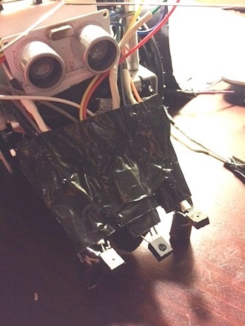
The line following robot in the video is the result of an exploratory processes which started with me building my own light sensing module and then ended with me purchasing a reflectance array sensor (Pololu QTR-3A) to achieve more consistent results. Before I get into the process let me explain the finished robot seen here:
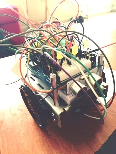
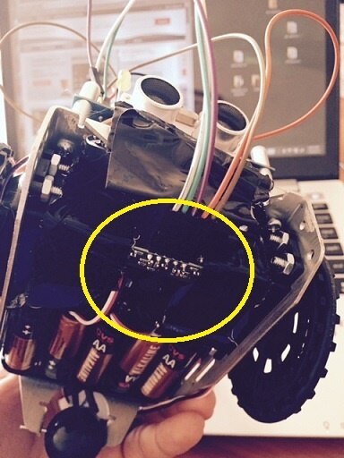
I've removed a lot of the attachments from the original Blambo Bot Delux to clean up the breadboard on top of the robot for experimentation with line following. There are 5 lights at the top of the robot indicating if one of the three sensors below is positioned directly above a black line. The green and red LED are initially used to indicate the beginning and the end of the calibration period. The yellow circle in the picture to the right shows where I mounted the QTR-3A reflectance array to thechassis by using duck tape. How creative!
The sensor is tiny but surprisingly it is able to cover a broad range of reflective space under the robot and this allows it to follow black lines when code is written like such:
#include <QTRSensors.h>
#include <SPI.h>
#include<Servo.h>


Servo servoLeft;
Servo servoRight;


#define NUM_SENSORS            3  // number of sensors used
#define NUM_SAMPLES_PER_SENSOR  4  // average 4 analog samples per sensor reading
#define EMITTER_PIN            9  // emitter is controlled by digital pin 2


// sensors 0 through 5 are connected to analog inputs 0 through 5, respectively
QTRSensorsAnalog qtra((unsigned char[]) {0, 1, 2},
  NUM_SENSORS, NUM_SAMPLES_PER_SENSOR, EMITTER_PIN);
unsigned int sensorValues[NUM_SENSORS];


int green = A3;
int red = A4;


int leftled = 5;
int centerled = 4;
int rightled = 3;


int r = 0;
int l=0;
int c=0;


void setup()
{


  delay(500);
  pinMode(13, OUTPUT);
  pinMode(red, OUTPUT);
  pinMode(green,OUTPUT);

  pinMode(leftled,OUTPUT);
  pinMode(centerled,OUTPUT);
  pinMode(rightled, OUTPUT);

  digitalWrite(red, HIGH);    // turn on Arduino's LED to indicate we are in calibration mode
  digitalWrite(green,LOW);

  for (int i = 0; i < 400; i++)  // make the calibration take about 10 seconds
  {
    qtra.calibrate();      // reads all sensors 10 times at 2.5 ms per six sensors (i.e. ~25 ms per call)
  }
  digitalWrite(red, LOW);    // turn off Arduino's LED to indicate we are through with calibration
  digitalWrite(green,HIGH);

  // print the calibration minimum values measured when emitters were on
  Serial.begin(9600);
  for (int i = 0; i < NUM_SENSORS; i++)
  {
    Serial.print(qtra.calibratedMinimumOn[i]);
    Serial.print(' ');
  }
  Serial.println();

  // print the calibration maximum values measured when emitters were on
  for (int i = 0; i < NUM_SENSORS; i++)
  {
    Serial.print(qtra.calibratedMaximumOn[i]);
    Serial.print(' ');
  }
  Serial.println();
  Serial.println();
  digitalWrite(centerled,HIGH);
  delay(1000);

  servoLeft.attach(7);
  servoRight.attach(8);
}


void loop()
{


DECISION();
MOVEMENT();


}


void backward(){
  servoLeft.writeMicroseconds(1700);
  servoRight.writeMicroseconds(1300);
  delay(10);


}


void slowbackward(){
  servoLeft.writeMicroseconds(1600);
  servoRight.writeMicroseconds(1400);


}


void left(){
  servoLeft.writeMicroseconds(1300);
  servoRight.writeMicroseconds(1300);


    //  qtra.read(sensorValues); instead of unsigned int position = qtra.readLine(sensorValues);
  unsigned int position = qtra.readLine(sensorValues);


}


void slowleft(){
  servoLeft.writeMicroseconds(1400);
  servoRight.writeMicroseconds(1400);


}


void right(){
  servoLeft.writeMicroseconds(1700);
  servoRight.writeMicroseconds(1700);


  //  qtra.read(sensorValues); instead of unsigned int position = qtra.readLine(sensorValues);
  unsigned int position = qtra.readLine(sensorValues);


}


void slowright(){
  servoLeft.writeMicroseconds(1600);
  servoRight.writeMicroseconds(1600);
}


void forward(){
  servoLeft.writeMicroseconds(1300);
  servoRight.writeMicroseconds(1700);
  //  qtra.read(sensorValues); instead of unsigned int position = qtra.readLine(sensorValues);
  unsigned int position = qtra.readLine(sensorValues);


}


void pivotleft(){
  servoLeft.writeMicroseconds(1500);
  servoRight.writeMicroseconds(1700);
}


void pivotright(){
  servoLeft.writeMicroseconds(1300);
  servoRight.writeMicroseconds(1500);


}


void slowforward(){
  servoLeft.writeMicroseconds(1400);
  servoRight.writeMicroseconds(1600);
}


void stop(){
  servoLeft.writeMicroseconds(1500);
  servoRight.writeMicroseconds(1500);
}


void CENTERLIGHT(){
  digitalWrite(centerled,HIGH);
    digitalWrite(rightled,LOW);
    digitalWrite(leftled,LOW);

}


void LEFTLIGHT(){
  digitalWrite(leftled,HIGH);
    digitalWrite(centerled,LOW);
    digitalWrite(rightled,LOW);
}


void RIGHTLIGHT(){

  digitalWrite(rightled,HIGH);
    digitalWrite(centerled,LOW);
    digitalWrite(leftled,LOW);

}


void DECISION()
    {
  // read calibrated sensor values and obtain a measure of the line position from 0 to 5000
  // To get raw sensor values, call:
  //  qtra.read(sensorValues); instead of unsigned int position = qtra.readLine(sensorValues);
  unsigned int position = qtra.readLine(sensorValues);


  if (position >1030){
    RIGHTLIGHT();
    r=1;
    l=0;
    c=0;


  }

if (position <970){
  LEFTLIGHT();
  l = 1;
  r=0;
  c=0;


  }


if (position >=970 && position <=1030) {
    CENTERLIGHT();

    c=1;
    r=0;
    l=0;

}


Serial.println(); // uncomment this line if you are using raw values
Serial.println(position); // comment this line out if you are using raw values
}


void MOVEMENT(){
  if (l==0 && c == 0 && r==1){
    digitalWrite(red,HIGH);
    digitalWrite(green,LOW);
    left();
  }
  if (l==1 && c == 0 && r==0){
    digitalWrite(green,HIGH);
    digitalWrite(red,LOW);
    right();
  }
    if (l==0 && c == 1 && r==0){
    digitalWrite(green,LOW);
    digitalWrite(red,LOW);
    forward();
  }

}
Line 1 is where I imported the QTR library. Reference this link HERE
Once the library was installed I began to try and understand how the sensor works by looking at the "QTRA Example" file. I realized from this code that the "position variable" was the key to achieving line following. In line 231 I have used this for my robot by calling "qtra.readLine" as equal to the position of a give sensor (declared through "SensorRead").
This is quite a handy chunk of code because it provides an estimation of where the line is relative to each sensor and it also records what sensor last saw the line. In the code, this is done by scaling the sensor array readings out of 2000 (because there are only 3 sensors used in my case). With a reading of 0 meaning the left sensor is right over the black line, 1000 being the middle sensor is right over the line, and 2000 as the right sensor is right over the line.
Lines of code 234-260 demonstrate how these values are translated by "if" statements into binary digits, 1 and 0, per variables representing the center ("c"), left ("l") and right ("r") positions. Once binary combinations of 1 and 0 are achieved this is further translated into servo motor movement by the MOVEMENT() function beginning in line 268.
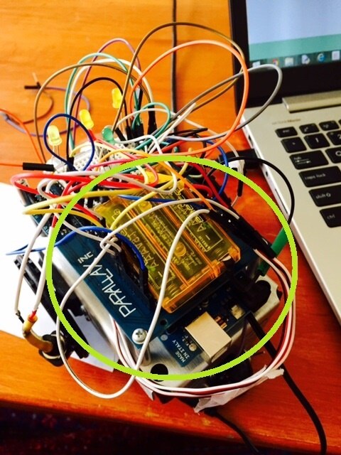
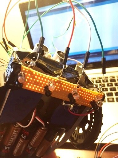
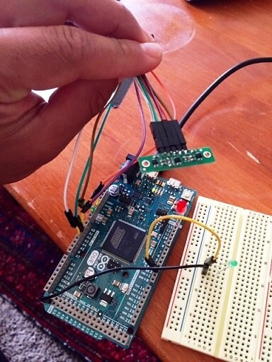
An important thing to note about the robot is that the servo motors need to have a separate power source to function correctly. If a separate power source is absent then the robot locks up in one direction and the sensor doesn't give more than one reading. I only realized this late into the process of building my line following robot and, in retrospect, this is probably why some of my DIY sensor attempts didn't work. The picture below has a circle around the external power source used; 3 AAA batteries which fit comfortably on top of the robot and I soldered on a button to turn the motors on and off:
This technique of using 1 and 0s to represent sensor readings is used because, personally, it helps me visualize where the line is and also because it was what i used during the development process up to the finished product.
The Development Process - MY LINE FOLLOWING EVOLUTION:
"THE TRIPOLE WALRUS" (IR Receiver/Pairs)
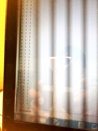
Included with the Parallax robot kit there are two IR receiver pairs. They work by detecting a drop off an edge when the IR signal has nothing to rebound off and then, as a result the receiver has nothing to read. This can be understood as the receiver reading 1 when there is a signal given by a the IR signal bouncing off an object and then 0 when there is nothing for the IR signal to reflect off of. I figured that for edge detection I should construct a 3rd IR receiver pair so that the middle of a line could be detected more readily. So, I went to Radioshack and purchased an IR led and an IR receiver and then made this- which would output values as seen on the right when an array of 3 sensors are hovered over a black vs white line:

It all looked good but what I realized is that it is difficult to the get IR LED to pulse at the correct frequency for the IR receiver to get a digital reading (at least with the sensor I made). Also, it was a pain to have to keep angling the IR receiver and led pair so a decent reflection could happen off of a given surface. All the angling of the sensors caused me to break multiple IR receivers and eventually I scrapped the idea all together. Now none of my IR receiver pairs work....I guess I broke them all....which means edge detection is finished for the Blambo Bot Delux...
"The SnagleTooth" (IR Sensor LED/ IR LED pair)
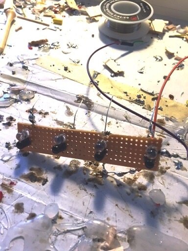
My failed attempt using IR receiver pair led me to try and take a second approach; this was to build a reflectance array using an IR led/ detector pair; these materials were bought from Radioshack and painstakingly soldered onto a cheap piece of plastic which I also purchased from Radioshack. These sensors worked much better than the IR receiver pairing ("Walrus") and Simulink was used to test out the analog readings of each sensor and then translate the signals into light. Simulink is great for this kind of thing because I can quickly pull together the blocks needed to achieve an analogue read and I can use the constructed system to see the threshold of values when the sensors hovered over different colored lines. This pictures show the Simulink code I used to test out the sensor:
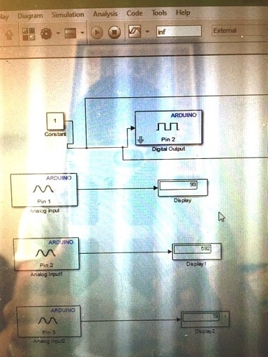
-The photo above on the left shows simple analog readings being taken for the sensors. Pin 2 is where the IR LED is so that is always on.
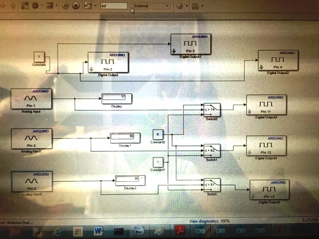
-The photo above on the right shows how the light readings turn a light on and off. Threshold values in the switch blocks were manipulated to achieve lighting on or off relative to a given value reading as a part of a manual calibration for the robot.
Using only 3 sensors at this point (because I broke on of the LEDs), this is the result of my Simulink Experiment:
Manual calibration, as I was messing around with in Simulink, is inconsistent when motors were added. It was very difficult to get my robot to follow a line as the manual calibrated values change when the robot was placed on the floor. Eventually I did develop a type of calibration in code which the sensor arrays would do prior to following the line on a specific floor, and there were moments when I felt things were successful:
However, after at least 1 week of trying I couldn't get my line follower to stay on a line and it was at this point I decided to cut my losses (in terms of time/not monetary at this point). This led to the:
Pololu QTR-3A Sensor!
Buying this gem was a great investment because all of a sudden I could get by robot to follow a line with ease. And I developed all the code within a day and the sensor fixed onto the Parallax chassis like a peach. For anyone thinking about adding line following to their robot I suggest going this route (buying a reflectance sensor array instead of making one). Buying this sensor was also cheaper rather than building my own. The only moment of difficulty was when I thought the sensor didn't work but after some time I realized that the servos needed to be powered separately; as was mentioned earlier.
Conclusion.....
Building line sensing into the Blambo Bot Delux Robot was a challenge but I learned a lot in the process. Power management has now become an issue for my robot so as I rebuild the Tara Bot Blambo Bot Delux so it incorporates the functions of the Line Follower 2 The Extreme Bot I'll take this into account. The goal for me, at this point, is also to think about how my robot can become functional for some useful purpose. Rather than being a novelty device that you'd pick up at Toys r'Us. In the future, I expect to combine line following, obstacle avoidance and light sensing to some interesting end.
On a side note my cat, Tara, is liking her robotic version more and more....

Top Comments