


A few months ago I delivered some Raspberry Pi CPD for the South Yorkshire CAS (Computing At School) hub. I was introducing the Raspberry Pi and demonstrating how it could be used in schools. At the time I was very impressed with the AV set up they had at the University. I was able to use a PC with my presentation, a Raspberry Pi running the software I was demonstrating and a visulaliser showing how i was setting up the RPi. All of which were presented on the screen.
This was something that was very useful for that presentation but would be even more useful in my lessons back at school. Unfortunately the school were not in a position to go out and purchase the expensive kit for me so I thought I would have to do without.
Along side the experiments with crystal formation I had planned to do for the test (Part 1, Part 2, Review) when I saw the case that was supplied with the kit on test I thought that I could set up a visualiser using the RPi for significantly less cost than a commercial one. The solid mounting provided in the case woud be the ideal platform to set up what i was looking for.
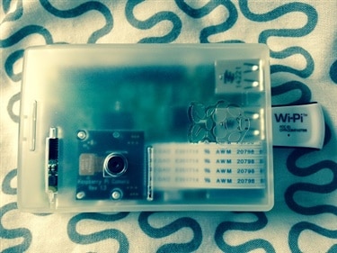
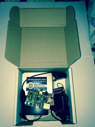
My initial plan was to use the case supplied and a clamp and clamp stand borrowed from the science department to hold it in place. When the kit arrived I realised that I could make a complete product with what had been supplied in the box.
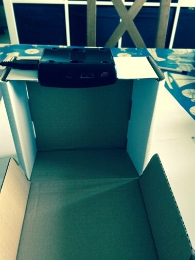
The first prototype is shown below (yes that is my bed this was taken 3 days after i had my appendiix removed):

This needed a little finessing with a craft knife to work; so a week on and I have been able to try out my idea. A little marking out with a pencil and a rough cut was made in the box.

Initially I intended to leave a thin strip on the outside to support the case but eventually that proved unneeded so it was removed. After several attempts at getting the gap the correct size a good fit was made.
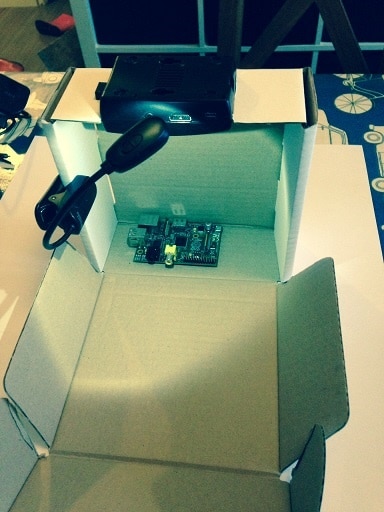
So with the case in place (the case pictured is a black version of the one in the kit that I had in the house, the original being stuck on on my bedroom window for side project 2) I added an eReader LED light I happened to receive for Christmas.
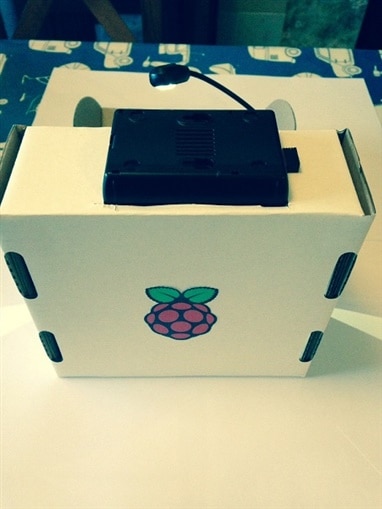
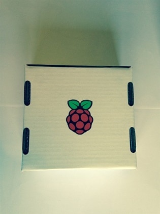
I then felt a little decoration was required so a RPi sticker was added to the rear of the box.
With the box completed I turned my attention to setting up the RPi to control the camera. My plan was to use a really simple program to control the camera and then add extra functionality later. My initial thoughts were to use a python script, however I have simplified the idea even further and control the camera using raspivid. As the camera is at 90 degrees to the subject the extension
-rot 90 is used to rotate the image. To keep the image on screen the extension -t x is used where `x` is the time in milliseconds.
this gives the full command:
raspivid -t 300000 -rot 90
So the initial set up was sorted with a single command line command. The time I chose is 5 minutes, this was a little arbitrary and could be changed to be longer or shorted initially(or terminated early using Ctrl+c).
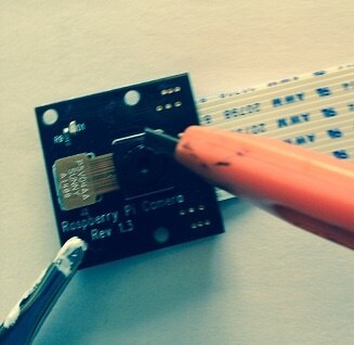
With the display working i needed to tackle the focal length of the camera. When shipped the minimum distance objects appear in focus is around 47cm. this box being significantly shorter meant I would need to change the focus of the camera. This is achieved by rotating the lens anticlockwise. Unfortunately the camera module is sold as a fixed focus unit so it is glued in place. The glue can be removed using a craft knife.
WARNING!!!
The camera module is sensitive to static and can be easily broken if attempting this. Particular care should be taken to avoid static and when trying to turn the lens it is important to hold the square part of the camera module to prevent it from braking off the board. The author takes no responsibility for camera board broken in this way, you have been warned. IF you are unsure about doing this the work around is to use a larger box or source a clamp stand.
If you do choose to go ahead then use a small sharp craft knife and a magnifying glass or helping hand could be useful.
Once the lens had been adjusted the build was complete. So I powered it back up and tested the Visual-Pi-ser with a small physical computing project.

The added bonus of using the box provided with the kit was that it doubles as a portable case, as the box construction the flap closes over the hole in the box made to fit the case. There is also plenty of room to store the RPi, power supply, light source and some small Physical computing bits and bobs for demonstrations
A full set of instructions on building your own Visual-Pi-ser can be found in my GitHub repository.

