


This robotic arm/line following robot is the conclusion to my summer project for the "Teacher's pet- educators road test." Believe me, this effort to create something original with a Parallax Robot and MATLAB/SIMULINK came a long way from where I first started.
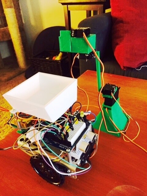
In all, my robotic arm is made up of 4 servo motors controlled by an Arduino Due; but the improvement from my last blog post is that the arm starts according to two options:
1. A remote button push (labeled "!" in the photo)
2. Pressure on a force resistance sensor which is"wired" into the movement of a robot (labeled a. in the photo)
I'll choose number two....and set off an autonomous, industrial process which dispenses rice krispeis.....

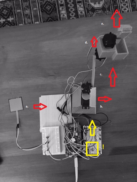
My device can be described in parts: the base, arm, hand, finger.
The relation between these part's timing is how the robotic arm achieves a grabbing motion towards rice krispies.
In fact, each part of the arm is timed differently going downwards to pick up the rice krispies than the sequence back up in order to stay out of the path of a moving, line following robot. The timing idea is represented by the photo (above/right) where "!" is a button press which causes the arm to dance through motion "b", "c", "d"."e" when moving down and then during the inverse directional movement going up, the pattern of movements then follows "d","c","b","e." Pressure on the force resistance sensor "a" causes the same chain of events as during the button press.
The colored boxes I drew in the photos below is my way of representing information in rectangles. What I have learned during the Teacher's Pet challenge is that this is exactly what MATLAB/SImulink in trying to do albeit, without any color. Below are images of the Simulink model loaded onto the Arduino Due controlling my robotic arm:
If you have MATLAB/SIMULINK, you can download the completed model HERE
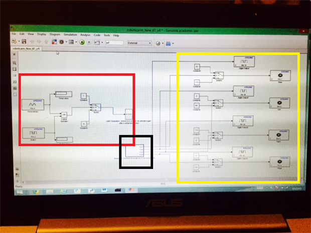
The model can be defined in 3 regions which flow from red-->black-->yellow.

Up close, the red block looks like the photo above; the force resistance sensor and button are in their respective boxes for Arduino pins (Pin 0 and Pin 2). A signal caused by these starting blocks pushes a value of 1 or 0 value through a "latch subsystem"; which is basically turning the robot on and then starting a running clock for when the robot can be started again:
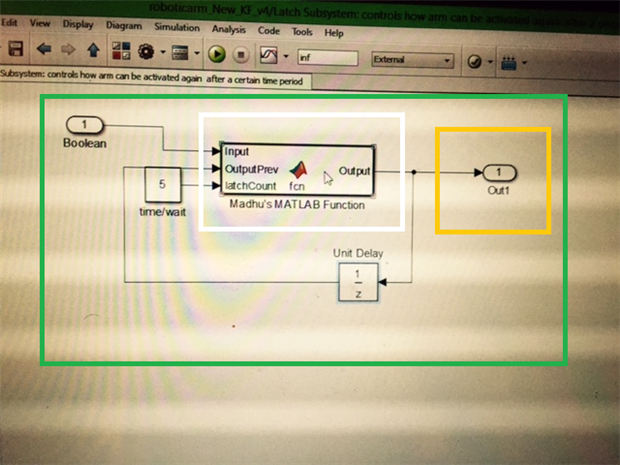
If you click into the "latch subsystem" the above photo is what you'd see. Inside the white box is a MATLAB function which Madhu from MATLAB/Mathworks helped me develop. I've never used MATLAB/SIMULINK before this road test so Madhu's understanding of how MATLAB code can be stored inside function blocks in Simulink was appreciated. It was also helpful to have someone tell me where certain Simulink blocks like "delays" are located because there are a lot programming blocks to consider inside the IDE.
T
When you click into the Madhu's MATLAB function, lines of code (above photo) count incremental gains of 0.25 sec. until a "latch" limit (in my case, which is set to 5 and exists outside the function block, in the photo a couple above as "time/wait") is reached. In this way, the code works like an upward counting egg timer which signals when your eggs are hard boiled and then when another egg can be plopped into the pot. Here is that code again in a format you can copy and paste into MATLAB:
function Output  = fcn(Input, OutputPrev, latchCount)


%#codegen


persistent count
if isempty(count)
    count = 0;
end
if count == 0
    Output = Input;
    if Input == 1
        count = count + 0.25;
    end
elseif count <= latchCount
    count = count + 0.25;
    Output = OutputPrev;
elseif count > latchCount
    Output = Input;
    count = 0;
else
    Output = 0;
end
When the timer is in progress another subsystem runs......
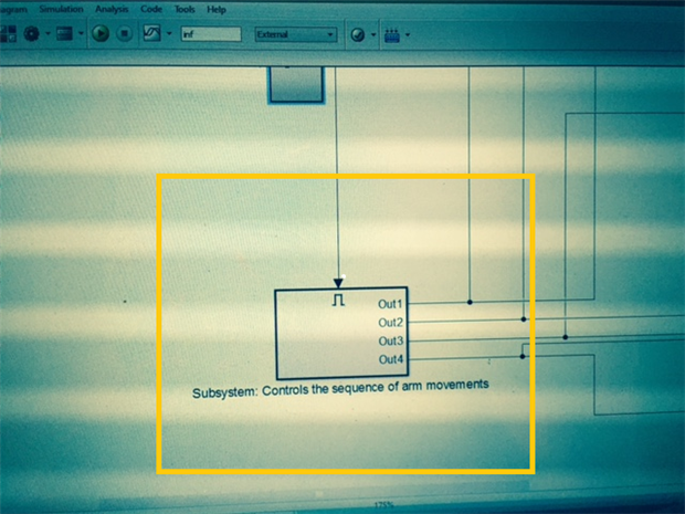
....double click the rectangle in the yellow box and this is what you'd see:
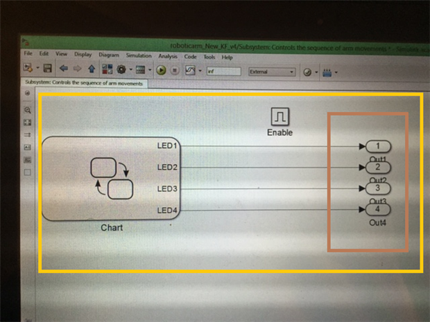
Inside is a chart block which contains a list of 4 LED lights being turned off in a pattern set to move along with the robotic arm's motion. Note: remember when I discussed "the movements of "b", "c", "d"."e" when moving down and then the inverse movement going up as "d","c","b","e."" hint, hint......

And yes, of course! The "on" and "off" of the LED lights corresponds to the movement up and down of a respective servo motor. In fact, I figured out that the timing of the servo motors by first controlling the timing of flashing LEDs.

Each servo on the arm can be in two possible positions, the angles of which are recorded in constant blocks in Simulink (see the photo above). The yellow and blue arrows are pairs of angles for each servo mirroring the "on" and "off" function of the LED lights; yellow is for the servo angle moving up (LED OFF) and then the blue for the servo angle moving downwards (LED ON).
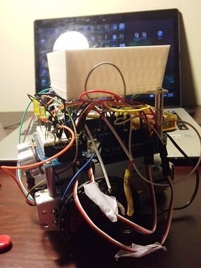
Inside The TaraBOTBlamboBotDELUX version "Line Follower to the Extreme" robot:
This line follower to the extreme was programmed in Arduino's development environment.
The ultrasonic sensor on the front of the robot is used with a line following routine. If you put your hand in front of the robot it will stop and if the hand is there to long then the TaraBotBLAMBObotDELUX (Line Follower to the Extreme version) reverses direction and continues to hug the line.
Unfortunately, Madhu and I never could get the Radio shack brand ultrasonic sensor I have to work in a Simulink models, therefore highlighting a limitation, convenience wise, when programming Arduinos with Simulink as opposed to the traditional Arduino IDE. Nonetheless,here is the final version of the code for my line following robot, Arduino style:
#include <QTRSensors.h>
#include <SPI.h>
#include<Servo.h>
class Ultrasonic //defining ultrasonic sensor object


{
  public:
  Ultrasonic(int pin);


        void DistanceMeasure(void);
  long microsecondsToCentimeters(void);
  long microsecondsToInches(void);


  private:
  int _pin;//pin number of Arduino that is connected with SIG pin of Ultrasonic Ranger.
        long duration;// the Pulse time received;


};
Ultrasonic::Ultrasonic(int pin)
{
  _pin = pin;
}


/*Begin the detection and get the pulse back signal*/
void Ultrasonic::DistanceMeasure(void)
{
    pinMode(_pin, OUTPUT);
  digitalWrite(_pin, LOW);
  delayMicroseconds(2);
  digitalWrite(_pin, HIGH);
  delayMicroseconds(5);
  digitalWrite(_pin,LOW);
  pinMode(_pin,INPUT);
  duration = pulseIn(_pin,HIGH);
}


/*The measured distance from the range 0 to 400 Centimeters*/
long Ultrasonic::microsecondsToCentimeters(void)
{
  return duration/29/2;
}
/*The measured distance from the range 0 to 157 Inches*/
long Ultrasonic::microsecondsToInches(void)
{
  return duration/74/2;
}


Ultrasonic ultrasonic(6);


Servo servoLeft;
Servo servoRight;


#define NUM_SENSORS            3  // number of sensors used
#define NUM_SAMPLES_PER_SENSOR  4  // average 4 analog samples per sensor reading
#define EMITTER_PIN            9  // emitter is controlled by digital pin 2


// sensors 0 through 5 are connected to analog inputs 0 through 5, respectively
QTRSensorsAnalog qtra((unsigned char[]) {0, 1, 2},
  NUM_SENSORS, NUM_SAMPLES_PER_SENSOR, EMITTER_PIN);
unsigned int sensorValues[NUM_SENSORS];


int green = A3;
int red = A4;


int leftled = 5;
int centerled = 4;
int rightled = 3;


int r = 0;
int l=0;
int c=0;
int counter = 0;


int leftDistance;


int rightDistance;


int centerDistance;//distances on either side- for measuring distance and making decisions


int collisionThresh = 8;


unsigned long previousMillis = 0;
const long interval = 5000;          // interval at which to blink (milliseconds)
unsigned long stoptime=0;


void setup()
{


    // print the calibration minimum values measured when emitters were on
  Serial.begin(9600);

  delay(500);
  pinMode(13, OUTPUT);
  pinMode(red, OUTPUT);
  pinMode(green,OUTPUT);

  pinMode(leftled,OUTPUT);
  pinMode(centerled,OUTPUT);
  pinMode(rightled, OUTPUT);

  digitalWrite(red, HIGH);    // turn on Arduino's LED to indicate we are in calibration mode
  digitalWrite(green,LOW);

  for (int i = 0; i < 400; i++)  // make the calibration take about 10 seconds
  {
    qtra.calibrate();      // reads all sensors 10 times at 2.5 ms per six sensors (i.e. ~25 ms per call)
  }
  digitalWrite(red, LOW);    // turn off Arduino's LED to indicate we are through with calibration
  digitalWrite(green,HIGH);

  digitalWrite(centerled,HIGH);
  delay(1000);

  servoLeft.attach(7);
  servoRight.attach(8);

  int sensorleft = sensorValues[0];
  int sensorcenter = sensorValues[1];
  int sensorright = sensorValues[2];


}


void loop()
{

  int sensorleft = sensorValues[0];
  int sensorcenter = sensorValues[1];
  int sensorright = sensorValues[2];

  Serial.print(sensorleft);
  Serial.print(" ");
  Serial.print(sensorcenter);
  Serial.print(" ");
  Serial.println(sensorright);


long RangeInInches;

    ultrasonic.DistanceMeasure();// get the current signal time;

    RangeInInches = ultrasonic.microsecondsToInches();//convert the time to inches;


  if (RangeInInches<3){

    while (counter <= 5){
    stop();
    delay(500);
    counter++;

    ultrasonic.DistanceMeasure();// get the current signal time;

    RangeInInches = ultrasonic.microsecondsToInches();//convert the time to inches;

    if (RangeInInches >=3){
    counter=7;
    }
  }

  while(counter == 6){
    right();
    delay(900);
    counter++;
  }

  }


else{
  counter = 0;
  DECISION();
  MOVEMENT();
}
}


//////////////////////////////////////////////////////


void backward(){
  servoLeft.writeMicroseconds(1700);
  servoRight.writeMicroseconds(1300);


}


void left(){
  servoLeft.writeMicroseconds(1300);
  servoRight.writeMicroseconds(1300);


  //  qtra.read(sensorValues); instead of unsigned int position = qtra.readLine(sensorValues);
  unsigned int position = qtra.readLine(sensorValues);


}


void right(){
  servoLeft.writeMicroseconds(1700);
  servoRight.writeMicroseconds(1700);


  //  qtra.read(sensorValues); instead of unsigned int position = qtra.readLine(sensorValues);
  unsigned int position = qtra.readLine(sensorValues);


}


void forward(){
  servoLeft.writeMicroseconds(1300);
  servoRight.writeMicroseconds(1700);
  //  qtra.read(sensorValues); instead of unsigned int position = qtra.readLine(sensorValues);
  unsigned int position = qtra.readLine(sensorValues);


}


void stop(){

  servoLeft.writeMicroseconds(1500);
  servoRight.writeMicroseconds(1500);


}


void CENTERLIGHT(){
  digitalWrite(centerled,HIGH);
    digitalWrite(rightled,LOW);
    digitalWrite(leftled,LOW);

}


void LEFTLIGHT(){
  digitalWrite(leftled,HIGH);
    digitalWrite(centerled,LOW);
    digitalWrite(rightled,LOW);
}


void RIGHTLIGHT(){

  digitalWrite(rightled,HIGH);
    digitalWrite(centerled,LOW);
    digitalWrite(leftled,LOW);

}


void DECISION()
    {
  // read calibrated sensor values and obtain a measure of the line position from 0 to 5000
  // To get raw sensor values, call:
  //  qtra.read(sensorValues); instead of unsigned int position = qtra.readLine(sensorValues);
  unsigned int position = qtra.readLine(sensorValues);


  if (position >1030){
    RIGHTLIGHT();
    r=1;
    l=0;
    c=0;


  }

if (position <970){
  LEFTLIGHT();
  l = 1;
  r=0;
  c=0;


  }


if (position >=970 && position <=1030) {
    CENTERLIGHT();


    c=1;
    r=0;
    l=0;

}


Serial.println(); // uncomment this line if you are using raw values
Serial.println(position); // comment this line out if you are using raw values
}


void MOVEMENT(){
  if (l==0 && c == 0 && r==1){
    digitalWrite(red,HIGH);
    digitalWrite(green,LOW);
    left();
  }
  if (l==1 && c == 0 && r==0){
    digitalWrite(green,HIGH);
    digitalWrite(red,LOW);
    right();
  }
    if (l==0 && c == 1 && r==0){
    digitalWrite(green,LOW);
    digitalWrite(red,LOW);
    forward();
  }
}
You may have already noticed that my line following robot has a white bowl to collect precious pieces of rice krispies as they fall from the sky. This bowl, like the robotic arm, was 3D printed on a Printerbot Makers edition which in itself is a miracle with models coming unstuck from the printing bed so often.

In conclusion, I've created an object kind of like the one below:

- In fact, I have already employed the robotic arm during school ice breaker activities because nothing opens people up to discussion like a robot
- Also, I have used the arm for my 3D printing class when I showed students how I made mechanical parts with Sketchup
- Furthermore, the value of making a robotic arm/line following robot is for visualizing the future of educational tasks in the classroom
- Additionally, a mini line following robot + robotic arm system which delivers rice krispes may revolutionize the way people eat breakfast
I'd like to thank element14.com and MATLAB/SIMULINK for running this educators road test. I've learned a lot about a new programming language, MATLAB/SIMULINK, as well as the capabilities of the Parallax robot chassis.
Top Comments