


Hi folks!!
In my previous blog post, we've seen the basics of object detection and tracking.....both by color and also edge detection. In order to understand what I'm going to convey through this blog post, I would like you to first make yourself comfortable with the basics provided in earlier blogs.
Well, in this post, let us see how to make a pan and tilt module using a couple of micro servos and then use it to control the amount of Pan and tilt by taking the tracking information as a feedback from the Pi cam and also measure the distance from the object of interest, while tracking it.
Making a Pan and Tilt module:
You will need two servo....preferably micro servos as torque requirement is very less and you can directly power it from micro controller board like arduino. I choose arduino to control it instead of using Raspberry Pi because Pi just has provision for attaching one PWM pin. However, we have two servos to control and I'm having a spare Arduino. So, instead of buying an accessory to include more PWM pins, I decided to use the Arduino. Below, is the picture of the micro servo I've used and you can get it for like $4-$6.

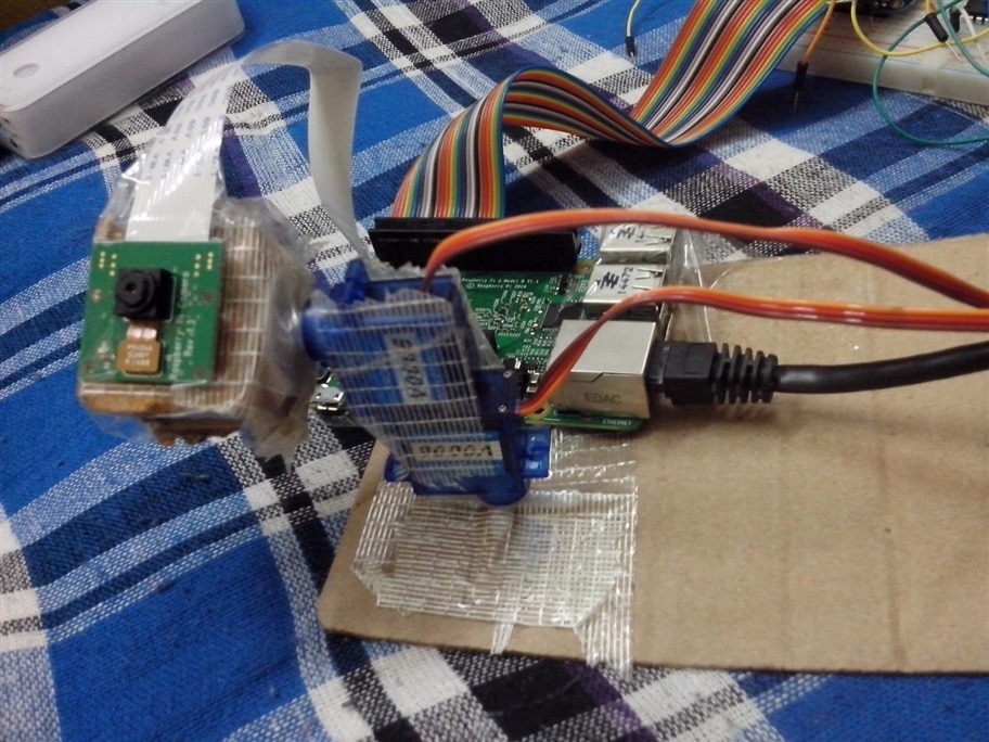
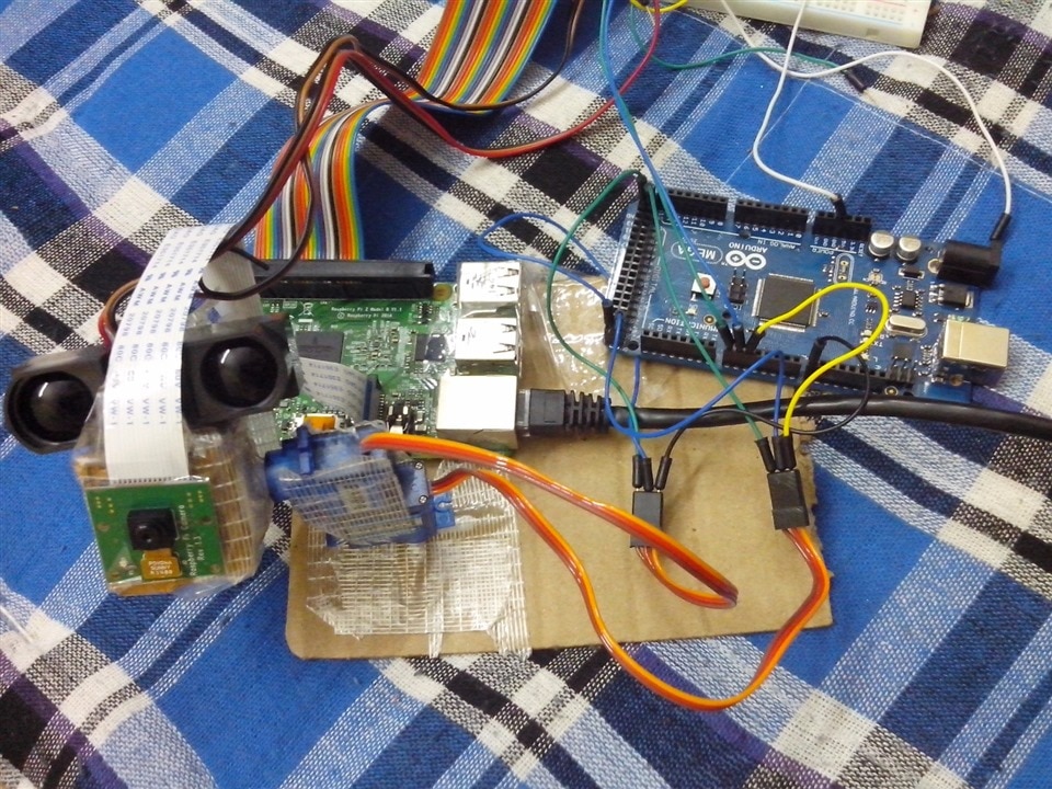
Apart from the servos and the micro-controller to control them, we need some mechanical structure as a platform to stage these servos. Now, take a look at the module I've made. Go ahead, make fun of it. I've made it in like 25 min with the help of things I could find in my storage. I've used a card board sheet as a platform for the module and used fiber reinforced duct tape to hold everything in place. But remember, if it works, it works.
Programming the Raspberry Pi :
All we have to do is perform an object detection, track the object and convey that information to arduino via Serial Ports i.e Tx and Rx. The rest of the job to control the servos depending on the data obtained from the Pi is left to the arduino.
Below is the code you've seen in the previous post; to perform an object detection and track by using color detection.
First, we initiate handles for Pi, cam, mcp3008 and serial transfer at 9600 Baud, to which arduino is also set. You should note that the file name is track.m and the command edit(file_name) constantly modifies the tracking pattern. We then take a set of snapshots and extract the RGB components from it and set it to detect green instead of blue as in previous post. We then accordingly threshold the image and find the mean of the center of the positive id of the detection. Transfer this information to the arduino as Serial write after converting it to appropriate code for controlling the Servo, which I'll explain in second half of this post. And later take the distance of object in front of distance sensor and Pi cam.
clear rpi
clear cam
rpi=raspi();
clear mcp3008;tot=0;
mcp3008 = raspi.internal.mcp3008(rpi, 'CE0');
myserialdevice = serialdev(rpi,'/dev/ttyAMA0',9600);
cam = cameraboard(rpi, 'Resolution', '640x480');
cam.Rotation=180;
edit('track.m');thresh=40;
figure(1);
for i = 1:100
    %% Extract RGB color components
    img=snapshot(cam);
r = img(:,:,1);
g = img(:,:,2);
b = img(:,:,3);

%% Calculate green

justGreen = g - r/2 - b/2;

%% Threshold the image

bw = justGreen > thresh;

%% Find center

[x, y] = find(bw);
if ~isempty(x) && ~isempty(y)
    xm = round(mean(x));
    ym = round(mean(y));
    fprintf('x-coordinate: %d\n', xm);
    fprintf('y-coordinate: %d\n', ym);
    if xm<150 && xm>0
        write(myserialdevice,['3,']);
    elseif xm>350 && xm<500
        write(myserialdevice,['-3,']);
    else
        write(myserialdevice,['0,']);
    end
    if ym<250 && ym>0
        write(myserialdevice,['-3']);
    elseif ym>350 && ym<700
        write(myserialdevice,['3']);
    else
        write(myserialdevice,['0']);
    end
    %% Create a red dot
    xx = max(1, xm-5):min(xm+5, size(bw, 1));
    yy = max(1, ym-5):min(ym+5, size(bw, 2));
    bwbw = zeros(size(bw), 'uint8');
    bwbw(xx, yy) = 255;

    %% Create output image

    img(:,:,1) = uint8(r + bwbw);
    img(:,:,2) = uint8(g - bwbw);
    img(:,:,3) = uint8(b - bwbw);
end
    subplot(211);
    imagesc(img);
    subplot(212);
    imagesc(bw);
    drawnow;
end

for i = 1:50
    voltage = readVoltage(mcp3008, 0);
    fprintf('Voltage = %0.2f\n', voltage);
    dig = voltage*(1023/5);
    distance=28250/(dig-229.5);
    fprintf('Digital value = %0.2f\n', dig);
    tot=tot+distance;
    pause(0.001);
end
avg=tot/50;
fprintf('distance in cm is %0.2f\n', avg);
Programming Arduino to control Pan n Tilt module:
Now, after making necessary connections like power, Serial and PWM connections, burn up the code which initially declares handles for each of the two servos. Then , in the setup function, we assign servo's PWM connections to these handles and define a baud which we chose to be 9600. In the loop function, we take in the Serially sent values using Serial.parseInt function, not the general Serial.read function. This is because, the Serial.parseInt function automatically searches for numbers in the information sent without any complications. we then write these values to each of the Servo handles accordingly. Take a look a the code below.
#include <Servo.h>

Servo myservo1;
Servo myservo2;

int x,y,a=90,b=90;

void setup()
{
  myservo1.attach(2);
  myservo2.attach(8);
  Serial.begin(9600);
  }
void loop()
{   while(Serial.available()){
  x=Serial.parseInt();
  y=Serial.parseInt();
  Serial.println(x);
  Serial.println(y);
  a=a+x;
  b=b+y;
  myservo1.write(b);
  myservo2.write(a);
delay(2);
}}
The code works just fine but when sometimes it gets junk from serial communication, it may go wild, then you will have to reset the whole thing again.
I will be uploading the video showing the camera following the object like an eye (currently having a bad net connectivity to upload a video). My project was to develop a 3D reconstruction of the image in front of camera but after all it seems that it can only be done if either there are 2 or more camera or when the object of interest is moving considerably. In the absence of these cases, we cannot develop a point cloud for image reconstruction and thus cannot project a 3D image of it. So, in practical scenario, the object of interest might not move that much and hence, we cannot obtain what we want. So, I justified the title Virtual Eye System by selecting an object of interest and following it by tracking it with the help of Pan and Tilt module and we can modify it in such a way that it can track a particular student while taking an exam and alarms if the student is moving or peeping in to others papers. This can also be developed to use as a field judge in a match of tennis or badminton when the tennis ball or shuttle *** goes outside the arena when playing without the net and boundary markings. Or it can be used in the Table tennis or Tennis practice dummy machine's sensory system while playing with a human. Applications are only limited to the thoughts.