

.jpg)

Digital circuits use a clock to dictate the timing of operations. A clock is a signal that oscillates between high and low states at a regular rapid interval, serving as the timing reference to synchronize the activities of different components. Because the components of a digital circuit all operate based on the same clock, it needs to be stable and predictable, with as little jitter as possible.
Jitter is defined as short-term fluctuations in the timing of the clock pulse, where the rising and falling edges deviate from their ideal positions. In short, the rising and falling edges can be slightly early or slightly late, affecting the timing of the circuit. These fluctuations can be small, sometimes in the nanoseconds, but any amount of jitter can cause anomalies in digital circuits.
What does a Clock do in a Digital Circuit?
Most digital circuits run on clocks. All of the digital components are synchronized by the clock signal, ensuring that they operate in unison and avoid unpredictable behaviors. When looking at the specifications for the processor in a computer, there is a “GHz” rating, which refers to the clock speed (1GHz is equivalent to one billion clock cycles per second). Digital components are triggered by either the rising or falling edge of the clock signal. With a 3.8GHz processor, 3.8 billion instructions can be carried out per second. It's not so simple, however, as modern processors may have more than one core, and many processors and controllers have the ability to process instructions in parallel. That 3.8 billion number can be much higher.
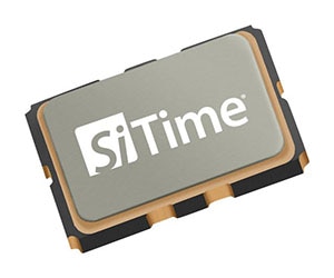
At the heart of a digital clock is the oscillator, a component that generates a fixed frequency signal that the clock signal is derived from. There are various types of oscillators, including quartz or other crystal-based oscillators, VCO (Voltage-Controlled Oscillator), VXCO (Voltage-Controlled Crystal Oscillator), and Temperature-Compensated Crystal Oscillator (TCXO). Atomic clocks, frequently used for syncing GPS and telecommunications equipment, use rubidium to control the oscillator's frequency.
What is Jitter and How does it Affect a Digital Circuit?
Jitter is the term used to describe the variation in the timing of a signal. In terms of music, jitter would be similar to a metronome where the ticks are sometimes early and sometimes late, wreaking havoc on a band or orchestra trying to play in sync. Like defective a metronome, a jittery clock signal can cause major problems in a digital circuit. Digital circuits require precision in their timing; the presence of jitter can affect performance and reliability, causing various problems, including:
Timing Violations: Jitter can cause timing violations, where the edges of signals arrive earlier or later than expected. This can result in incorrect data sampling, leading to errors in the system.
Data Corruption: In communication systems, jitter can cause data corruption. If the timing of a clock signal or data signal is not stable, it may lead to misinterpretation of data bits by the receiving components.
System Stability Issues: Jitter can impact the stability of a system, especially in high-speed applications.
Synchronization Problems: In systems that rely on synchronization between different components or subsystems, jitter can disrupt the proper coordination of operations. This can result in synchronization loss, affecting the functionality of the system.
Clock Recovery Issues: In communication systems where the receiver needs to recover the clock signal from the incoming data stream, jitter can make it challenging for the receiver to accurately recover the clock.
Performance Degradation: Jitter can degrade the overall performance of a digital circuit. This is particularly critical in applications where precise timing is essential, such as high-speed data transmission, digital signal processing, and real-time systems.
Phase Noise: Jitter is often associated with phase noise, which can introduce additional frequency components in the signal spectrum. This can interfere with the desired frequency components and affect the signal quality.
Quantifying Jitter in a Digital System
There are different metrics that are used to characterize jitter; these include cycle-to-cycle jitter, period jitter, and time interval error (TIE) jitter. These terms describe different aspects of the timing variations and are often used in the evaluation and specification of jitter in digital circuits and communication systems.
Cycle-to-Cycle (C2C) jitter is the variation in the duration of successive cycles of a periodic signal. It is expressed as the difference in time between the rising (or falling) edge of one cycle and the rising (or falling) edge of the next cycle. Figure 1 illustrates an example of cycle-to-cycle jitter.
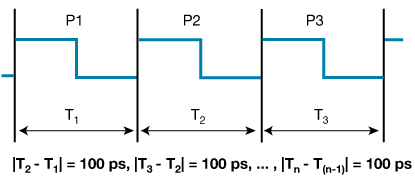
Figure 1: Cycle-to-cycle jitter (Source: NXP)
Cycle-to-cycle jitter is commonly used in digital logic designs where short-term variations in clock cycles can impact setup and hold times for data signals. However, because it does not show the difference in time for non-adjacent periods, it cannot be used to show frequency drift over time.
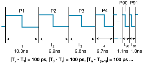
Figure 2: Cycle-to-cycle jitter with frequency drift
Period jitter is a measure of the variability in the time period of a periodic signal. It quantifies the difference in duration between the ideal clock period and the period of each individual cycle.
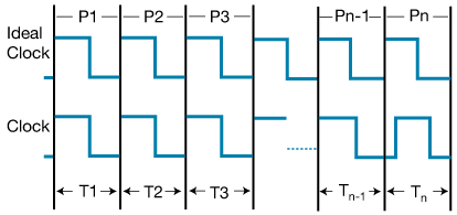
Figure 3: Period Jitter
Period jitter provides insight into the stability of the signal's frequency, and it is useful for characterizing long-term stability of a clock source. Because it is difficult to quantify an ideal period, the statistical mean of a large number of periods is usually used.
Time Interval Error (TIE) jitter is a measurement of the variations in the time intervals between consecutive edges of a periodic signal, or the difference in the actual time interval between two edges and the ideal time interval based on the average frequency. Figure 4 depicts an ideal clock with a jittery signal, and a comparison of the cycle-to-cycle, period, and TIE jitter measurements.
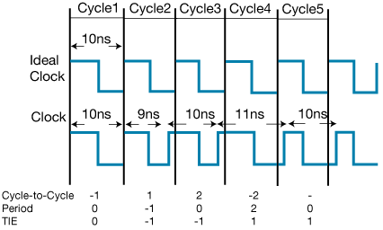
Figure 4: TIE as Related to Cycle-to-Cycle and Period Jitter
TIE jitter is often analyzed to understand the short-term variations in timing. It is often used in network synchronization applications where precise alignment of clocks is required across multiple devices.
What causes Jitter?
Jitter can be caused by a variety of factors, both within a system and in the external environment. Common causes of jitter include:
Clock Instability: The clock itself can be the source of trouble. Low-quality oscillators, temperature fluctuations, or electrical noise can all disrupt the clock's rhythm.
Noise and Interference: Electromagnetic interference (EMI) and radio-frequency interference (RFI) can introduce noise into the signal lines, leading to variations in signal transitions and contributing to jitter.
Component Delays: Different components in a circuit can introduce slight delays in processing data. If these delays are inconsistent, they can cause jitter.
Power Supply Noise: Variations or noise in the power supply voltage can affect the performance of clocking.
Temperature Variations: Temperature changes can affect the characteristics of electronic components and alter signal propagation times, leading to jitter.
Clock Distribution Issues: Unequal trace lengths and impedance mismatches in clock distribution networks can cause variations in signal arrival times.
Signal Reflections: Signal reflections in transmission lines can cause variations in signal transitions, resulting in jitter. Proper impedance matching and termination techniques can minimize reflections.
Component Aging: Aging of electronic components, especially components like capacitors and resistors, can lead to changes in their characteristics and contribute to jitter over time.
Some of these causes are deterministic, while the others are random. Deterministic jitter is caused by specific and identifiable sources, which include factors such as impedance mismatch, power supply ripple, and crosstalk. Deterministic jitter can typically be predicted and controlled. Random jitter is unpredictable and includes causes such as thermal noise or interference.
How to Keep a Digital Circuit Jitter-free
Crystals & Oscillators
Shop our wide variety of Crystals and Oscillators for digital circuits.
Don't forget to join our discussion.
Minimizing jitter in a digital circuit requires careful design and component selection. Start with the source: a stable and accurate oscillator with low phase noise and minimal inherent jitter. The clock distribution network should be optimized by minimizing trace lengths and crosstalk between signals. Distribute the clock signal evenly throughout the circuit using dedicated clock buffer chips and transmission lines. Signal reflections and other integrity issues can be reduced with proper termination techniques, controlled impedance, and high-quality PCB layout practices.
Optimize the circuit itself to make sure that the clock signal is not being degraded as it passes through components. Ensure balanced propagation delays through logic gates to avoid skewing or jitter in data timing. Utilize techniques like clock gating and pipeline design to manage clock usage and minimize clock skew. Implement clock buffering to isolate different sections of the circuit and prevent the loading of the clock source. Use clock conditioning circuits, such as phase-locked loops (PLLs) or delay-locked loops (DLLs), to clean and stabilize clock signals. These circuits can filter out jitter and provide a more stable output. Circuit simulation tools can be utilized to model jitter behavior and test your circuit before committing to hardware implementation.
Try to keep noise and temperature changes to a minimum. Pay attention to proper grounding to minimize ground bounce and reduce the impact of noise on signal lines. Ferrite beads, LC filters, and other passive filtering components can help in mitigating high-frequency noise. Shield sensitive clock signals from power supply noise and crosstalk from other digital signals. Use ground planes and differential signaling techniques to further enhance noise immunity. Finally, address thermal issues, as temperature variations can affect the performance of electronic components and introduce jitter.
Summing Up: Jitter in Digital Circuits
Stable and accurate clocking is essential in today's digital world. Like a bad drummer in a marching band, jitter can send your digital circuitry in the wrong direction. Just choosing a low jitter oscillator isn't enough; the rest of the circuit has to be up to par, including thermal management and proper shielding from any potential interference. Jitter can rear its ugly head at any moment; however, careful planning and design can keep the clock signal pure and steady, ensuring the smooth and reliable operation of digital circuits.
Has jitter ever affected your electronic devices or one of your digital circuits?
Please tell us in the Comments section below.