

Radio Frequency (RF) is an indispensable part of day-to-day wireless communication. RF technologies enable smartphone connectivity, Bluetooth, GPS navigation, and satellite communications. These everyday RF solutions typically operate at frequencies below 6 GHz. However, emerging technologies such as 5G networking, HPC/AI, and automotive 2.0 operate at larger higher bands, faster transmission speeds, and greater densities. Furthermore, the task of developing, qualifying, and validating FPGA boards for the technologies mentioned previously requires transceivers running at higher rates. Manufacturers of RF interconnects support this shift by favoring high-quality, precise, and performance-oriented RF products, capable of maintaining signal integrity and extremely low latency at higher frequencies. Precision RF interconnects support frequencies up to 110 GHz. When testing new designs, FPGA developers require precision test and measurement interconnect systems that maintain signal integrity at high frequencies. This Tech Spotlight article will focus on the Bulls Eye High Performance Test System from Samtec, which can maintain signal integrity up to 70 GHz with a compact test point footprint.
How do youTest a High-Speed FPGA?
Semiconductor manufacturers constantly search for the best interconnect solutions to characterize the high-speed transceivers found on FPGAs. PCB (Printed Circuit Board)-mount SMA (SubMiniature version A) connectors are used in many situations to interface with test equipment and route signals found in modern transceivers. Figure 1 shows a Xilinx Spartan-6 FPGA SP623 characterization kit, which features several PCB-mount SMA connectors.
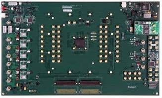
Figure 1: PCB-mount SMA connectors on the Xilinx Spartan-6 FPGA SP623 Characterization Kit (Image Source: Samtec)
This approach has worked for decades, as transceiver counts per FPGA were low, and PCB-mount SMA connectors supported data rates in the megabit and low gigabit per second range. As standard transceiver speeds surpassed 10 Gbps, the development of high-speed PCB-mount SMA connectors facilitated data rates up to 20 Gbps. However, another challenge sprung up due to Moore's Law: as ICs became more dense, with ever-shrinking process nodes, FPGA manufacturers increased transceiver counts on their high-speed semiconductor solutions. Characterization boards for these devices started requiring hundreds of PCB-mount SMA connectors.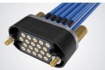
This approach has proven impractical, due to PCB size and cost constraints. Additionally, intricate PCB layouts are required to support the dozens of discrete SMA connectors. To overcome this challenge, the Bulls Eye High Performance Test System (Figure 2), designed as an SMA-replacement technology for test and measurement systems, was created by Samtec.
Figure 2: Bulls Eye High Performance Test Buy Now
The Bulls Eye®︎ Test Point System
Bulls Eye offers reduced board space and trace lengths, higher performance, and lower cost than traditional PCB-mount SMA connectors. The high-density array designs of the Bulls Eye system provide up to 4x the high bandwidth signals in the same PCB real estate when compared to SMA connectors. Figure 3 shows the size difference of a traditional SMA (on the left) and a Bulls Eye test point (on the right) when equipped with the same number of connectors. The system is available in single or multi-port, or as a high-density ganged connector. The compression interface to the board makes attaching and removing Bulls Eye from a PCB simple and eliminates soldering costs. The contacts satisfy high cycle counts, and replacement components are easy to order.
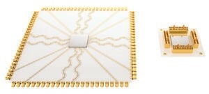
Figure 3: Traditional SMA (on the left) vs. Bulls Eye test point (on the right) (Image Source: Samtec)
Bulls Eye has found an additional use on FPGA boards. Because it enables so much PCB real estate to be saved, the test head can be positioned closer to the device. Figure 4 shows a Xilinx Kintex UltraScale FPGA KCU1250 Characterization Kit with eight Bulls Eye pads (as highlighted).
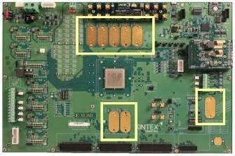
Figure 4: Xilinx Kintex UltraScale FPGA KCU1250 Characterization Kit with eight Bulls Eye pads (Image Source: Samtec)
The Bulls Eye system has advanced from 20 GHz (BDRA and BQRA series), to 50 GHz (BE40A series), to the present 70 GHz (BE70A series) designs, with a system up to 90 GHz under development. Table 1 summarizes the Bulls Eye family from Samtec. The system has evolved in performance and flexibility, and is available in microstrip and stripline transmission solutions. The BE70A series proprietary cable design provides 360° grounding around a spring-loaded pogo-pin contact. In addition, the test assemblies furnish a 1.85-mm connection to instrumentation. The BE40A series is a 50 GHz double row system with signal and ground pogo pins. End 2 connectors are 2.92 mm and 2.40 mm, available in microstrip or stripline PCB transmission, and are backward compatible with legacy, double row BDRA series 20 GHz solutions.
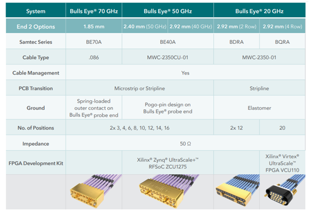
Table 1: Bulls Eye Test Point System Cross Reference Guide (Source: Samtec)
Applications
FPGA Connectors
Shop our wide variety of connectors for use in FPGA applications by Samtec.
Don't forget to take our poll.
A contributing factor to the popularity of the Bulls Eye High Performance Test System is that it complements FPGA characterization, evaluation, and development boards available in the market. Even the best boards have signal degrading vias, transmission lines, and connectors on the path from the device to the measuring instrument. Accurate de-embedding requires careful selection and measurement of calibration structures and interconnects. The following demonstrations and solutions show how the Bulls Eye system finds use in an FPGA board's environment.
A 70 GHz High-Performance Test Solution
This application example is based on Samtec's 56 Gbps PAM4 product demonstration platform, and highlights the advantage of using the Bulls Eye High Performance Test System. A Credo Bald Eagle 2 retimer (Figure 5a) transmits QPRBS31 pattern signals at 56 Gbps PAM4 data rates on five separate channels. These signals run differentially through about 1.5" of PCB trace to the 70 GHz Samtec BE70A Bulls Eye High Performance Test System. The signals travel from the Bulls Eye connector through phased match pairs of Samtec low-loss microwave coax cable, terminated with 2.4 mm precision RF connectors. These connectors mate to a Samtec SI evaluation board with NovaRay extreme density arrays. The signals travel from the coax cables, through the evaluation boards and Samtec NovaRay connector set, through another set of high-performance precision RF 2.4 mm cables, and back to the Bulls Eye connector. Finally, the data lanes circle back to the Credo Bald Eagle 2 receiver, recovering the data.
| Setup of 70 GHz high-performance test point system | Results of demonstration |
|---|---|
 |
 |
Figure 5a: Setup of 70 GHz high-performance test point system 5b: Results of demonstration (Image Source: Samtec)
Figure 5b shows the results. Specifically, there are zero errors, which is impressive for 56 Gbps PAM4 modulations. The Eye diagrams display signal amplitude with respect to time, and the resulting graphs resemble the shape of an eye. Increased noise will cause the eye to close, whereas, in an ideal scenario, the eye will appear wide-open. In the case of the Bulls Eye BE70A, the eye diagrams show eyes that are wide-open, with eye heights ranging from 180 to 248 mV, showing low Bit Error Rates (BER) of e-15.
112 Gbps PAM4 Silicon and Connector Evaluation Platform
The evolution to higher data rates places increasing demands on the design of practical SerDes (serializer/deserializer) channels. A PCB must be optimized for loss, reflections, crosstalk, and power integrity when dealing with 112 Gbps PAM4 signals. This is especially important for evaluation boards that let designers measure the performance of the silicon under varying load conditions. Samtec’s evaluation board features limited I/O count packages with short routing lengths, mated to minimal PCB interconnects, and an RF cable solution of the Bulls Eye High Performance Test System.
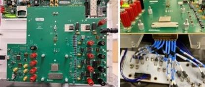
Figure 6: Powered evaluation board with Bulls Eye mounted opposite the test chip (Image Source: Image Source: Signal Integrity Journal)
The design of the silicon evaluation board (Figure 6) has a loss target (TX lane) of 3 dB at 28 GHz, including package, PCB, and 6" of BE70A cabling. An important design choice is to place the Bulls Eye block on the bottom side of the PCB, to allow closer positioning to the device package. This eliminates conflict with keep-outs for mounting holes, and results in PCB net lengths below 16 mm for the TX channels, each feeding an attached 6" compression mounted coax cable. With the overall topology decided, the package and PCB interconnects are modeled in iterative design cycles to optimize signal integrity for loss, reflection, and crosstalk, using ERL (effective return loss) as the primary design metric. The finished evaluation platform shows excellent BER results. Figure 7 shows the relative IL (insertion loss) contributions of the package, PCB, and cable assembly.
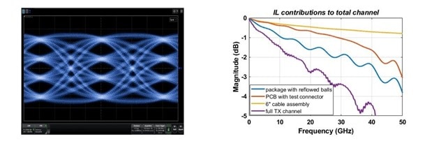
Figure 7: 106.25 Gbps PAM4 Tx measured Eye (left) and Channel IL breakdown (right) (Image Source: Signal Integrity Journal)
50 Ghz Bulls Eye SI Evaluation Kit
The 50 GHz Bulls Eye SI Evaluation Kit provides system designers, RF engineers, and SI engineers a solution for testing the 50 GHz Bulls Eye Double Row, High-Performance Test System. The 50 GHz Bulls Eye SI Evaluation Kit delivers a high-quality system with a robust mechanical design.
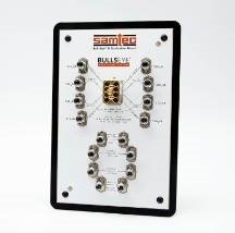
Figure 8. 50 GHz Bulls Eye SI Evaluation Kit (Image Source: Samtec)
The evaluation kit is available as a single PCB system with a compact form factor. Each PCB contains one compression interface that provides easy mating and eliminates soldering. The kit comes with one BE40A product Bulls Eye cable assembly. It can route high-frequency referential signals (8 total) from the BE40A product to high-precision RF connectors, and it supports multiple high-precision RF connector options (2.40 mm/2.92 mm SMAs).
Summing Up: The Bulls Eye®︎ FPGA Test System
in partnership with

The proliferation of new technologies such as 5G networking, HPC/AI, and automotive 2.0 has accelerated the demand for new test equipment. Bulls Eye is well suited for high-performance test-point applications because of its compression interface, better efficiency, small footprint, and high cycle count. The Bulls Eye system makes it easier and more convenient for FPGA developers to develop and test their systems, by reducing the size of evaluation boards and bringing the test head closer to the device under test.
Don't forget to join our discussion below:

