Take the Poll | Join our Discussion
sponsored by

Advancing RF Circuits Past 100 GHz
Many engineers can remember a time when RF circuits operating above 1 GHz was a rarity, confined to the domain of the experimental, one-off project. The evolution of Wi-Fi, mobile phones, and the license-free ISM (instrumentation, scientific, medical) 2.4 GHz band created the demand and consequent availability of components needed to thrive in the >1 GHz region. Systems have now moved even higher, with the 5 GHz Wi-Fi band showing activity due to crowding and interference issues at 2.4 GHz.
Technology has come a long way from the time when engineers believed that 40 GHz was the frequency range limit. Significant developments are inevitable as the telecommunications sector moves into mmWave frequency coverage. Semiconductors have advanced to the point where measurement devices need to cover the range from DC to 110 Ghz. The latest transceivers and antennas demand higher frequency to offer seamless data and accessibility to users. Connecting such devices requires cable assemblies and coaxial connectors that support frequencies past 110 GHz. This article explores mmWave frequencies and their characteristics, as well as challenges in designing connectors that support frequencies in excess of 100 GHz.
Millimeter and Sub-millimeter Wavelengths
The term millimeter-wave (mmWave) refers to 30 GHz to 300 GHz radio frequencies, which have wavelengths from 10 mm to 1 mm. Figure 1 shows signals with their wavelength (λ) and corresponding region in the electromagnetic spectrum. The mmWave is also known as the Extremely High-Frequency (EHF) range. Its high frequency and propagation characteristics make this range useful for various applications, such as high-speed broadband access and point-to-point wireless local area networks (WLANs). The Sub-mmWave band, also known as the terahertz or far-infrared band, is present between the mmWave band and infrared frequencies. There is a gap in the spectrum where historic challenges in signal generation and detection have prevented the development of applications. This little-used frequency band corresponds to frequencies in the range from 300 GHz to 3 THz, which have wavelengths from 100 μm.
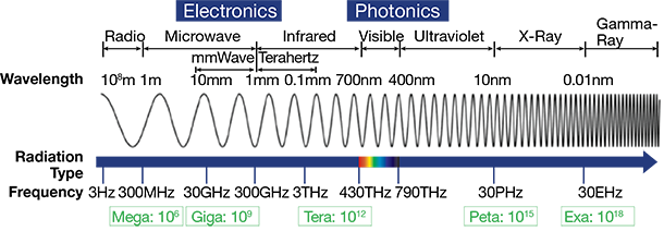
Figure 1: mmWave & Sub-mmWave Signals and common band names.
Source: IEEE
Since frequency is inversely proportional to wavelength, longer wavelengths have a lower frequency, and shorter wavelengths have a higher frequency. Very low frequencies have larger angles of diffraction, permitting them to convey signals around obstructions. The propagation characteristics of mmWave frequency bandwidth are noticeably different from the microwave frequency bands, especially with specifications such as path loss, rain attenuation, diffraction and blockage, foliage loss behaviors, and atmospheric absorption.
The diffraction angle is minute at mmWave frequencies, and most signals transmit via line-of-sight (LOS). The short wavelengths allow for active phased-array antenna designs, which can be implemented on a single chip, permitting optimization of gain along with the off-boresight links. Because of their attenuation and diffraction characteristics, millimeter waves are unsuitable for long-distance transmission, however, the smaller wavelengths enable antennas to be physically smaller, which enables more antennas per base station, increasing coverage. Connectivity is a challenge at mmWave frequencies in high-frequency applications, as higher speeds, increased bandwidth, smaller sizes, and greater density create specific demands on connector technology.
Challenges with Designing 100+ GHz Connectors
With frequencies approaching 100 GHz, precision in the design of connectors is crucial. A full 10 GHz wavelength is approximately 30mm long, while a 100 GHz wavelength is ten times smaller, at 3mm. The center connector on an mmWave cable might have a diameter of 0.5mm. At these frequencies, scratches that are too miniscule to be visible to the naked eye can cause significant degradation in the signal. This degradation can also be cause by dust particles. Additionally, the risk of degradation due to improperly seated connectors is much greater at mmWave frequencies.
Key electrical characteristics in cables include impedance (standard 50 Ω), VSWR (Voltage Standing Wave Ratio), maximum frequency, and Passive Intermodulation Distortion (PIM). The VSWR is of particular importance, as it determines how much of an electromagnetic wave will be reflected by the connector, leading to unwanted propagation and signal loss influences. .
Mechanical specifications such as engagement/disengagement forces, coupling nut torque, contact captivation, and durability determine the stability of the connection. Misalignment leads to unintended gaps within the connection, and this may lead to undesirable changes in the electrical characteristics of the connection, as shown in Figure 2. Operating temperature range, corrosion resistance, moisture, and other environmental characteristics must match connector deployment conditions.
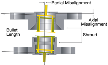
Figure 2: RF Connector alignment
Image Source: Belfuse
The manufacturing and installation of mmWave connectors and cables must be done with the utmost care and precision. Tightening a coaxial connector with a torque wrench is highly recommended; this guarantees a proper fit and eliminates any potential airgaps. Additionally, inspecting connector pairs with a microscope every time they are inserted is a good idea with mmWave applications. Once cables are in place, care must be taken to make sure they are not unseated.
Waveguide vs. Coaxial
Waveguide components remain the standard for >70 GHz frequencies and high-power signals. In contrast to coaxial components, a waveguide is non-resistive and has almost zero signal loss; almost all of the signal’s energy is conserved. Waveguides function more in specific frequency bands, however, and do not support broadband signals. For applications with limited frequency range, waveguides offer some advantages over coaxial solutions. Table 1 compares the electrical and physical parameter trade-offs of these two technologies.
Connectors and coaxial cables score big over waveguide in measurement applications, as they encompass broad bandwidths and not just designated waveguide bands. Coaxial cables are also more compact and weigh less, as well as being more flexible and easier to use.
| Parameter | Waveguide | Coaxial |
| Signal | Minimal Loss | Surface Loss |
| Time Domain | Limited Functionality because of Narrower Bandwidth | Broadband enabling Time Domain Functionality |
| Frequency Domain | Dispersion and Group Delay from TE/TM Modes | TEM Mode is Not Susceptible to Dispersion or Group Delay |
| Robustness | Rugged, Hard to Damage | Requires gentle handling and proper care |
| Setup Complexity | Complex; Fastening Screws, Alignment, Adapter Loss | Simple; Coax-to-Coax Interface |
Table 1: Waveguide and Coaxial Comparison
Image Source: Microwave Journal
Belfuse Cinch 100+ GHz Connectors
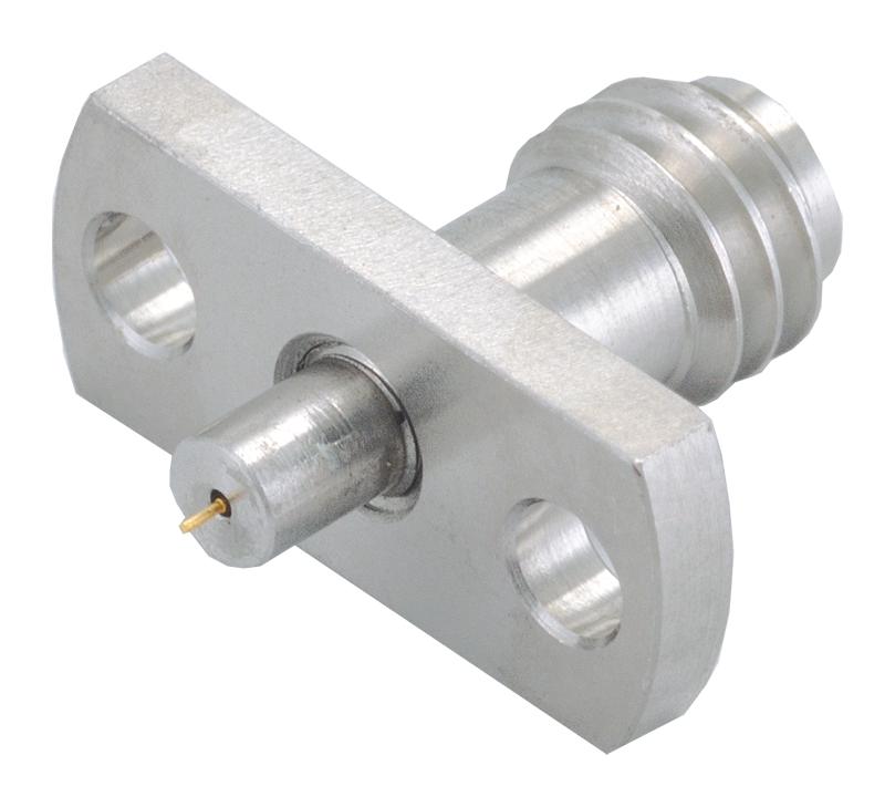
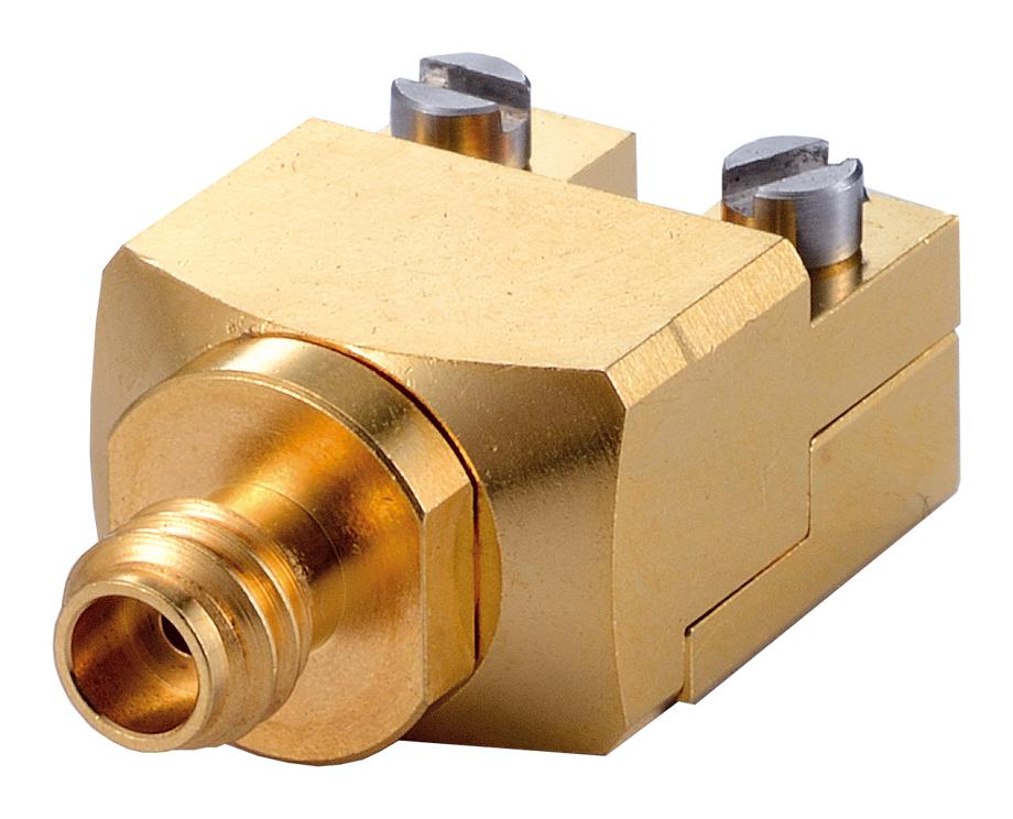
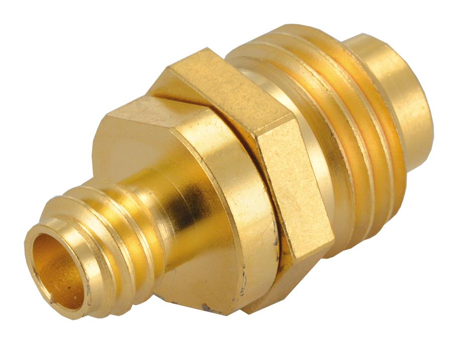
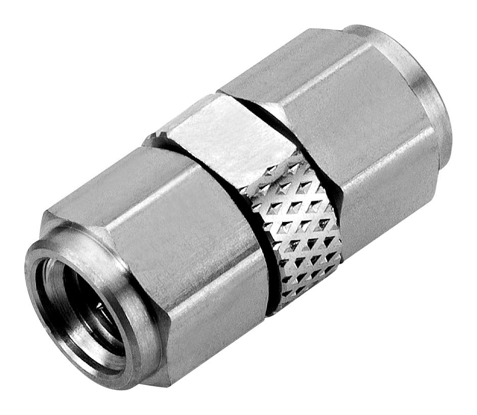
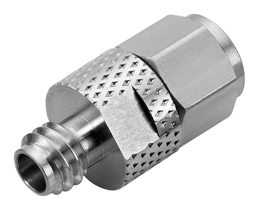
Cinch Connectivity Solutions, a Bel group company, has introduced the Johnson series of 1.0mm mmWave connectors and adapters. The Johnson mmWave portfolio includes end launch and panel end launch screw-on style connectors, sparkplugs, and in-series adapters, all with specifications that meet the requirements for 110 GHz and 5G testing in the semiconductor and test and measurement markets. The connectors and adapters are designed for operation from DC to 110 GHz with an impedance of 50 Ω.
RF Coaxial Connectors and Adapters Connectivity Solution
The Johnson 1.0mm Series Connector is designed for applications requiring high-frequency transmission. Frequencies of up to 110 GHz are supported with a VSWR performance of 1.38 Max. The connector mating interface is designed as per the IEEE P287 GPC standard. These connectors are well suited for signal integrity measurements, coplanar waveguide, SERDES, and substrate characterization, instrumentation test fixture equipment, and PC Board characterization.
End Launch Connectors
|
||
 |
 |
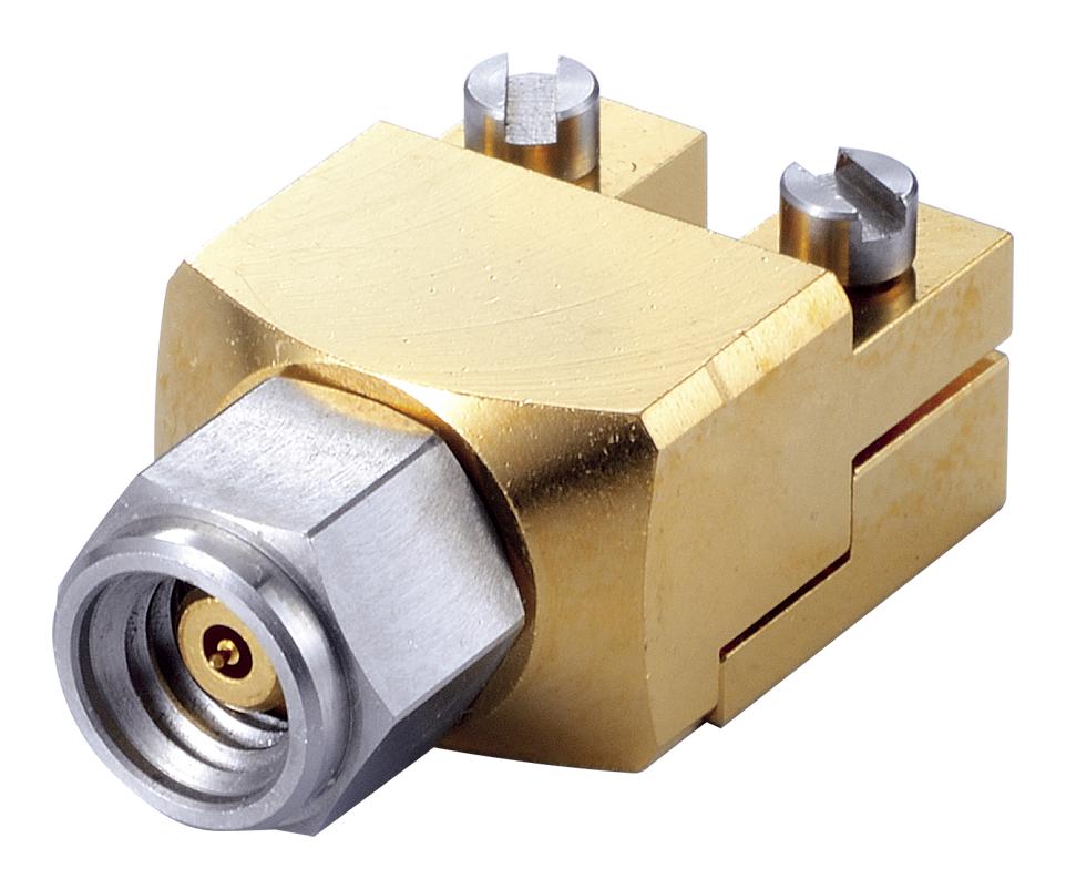 |
| Jack, Female End Panel | Jack, Female Screw-On Type | Jack, Male Screw-On Type |
Sparkplug Connectors
|
|
 |
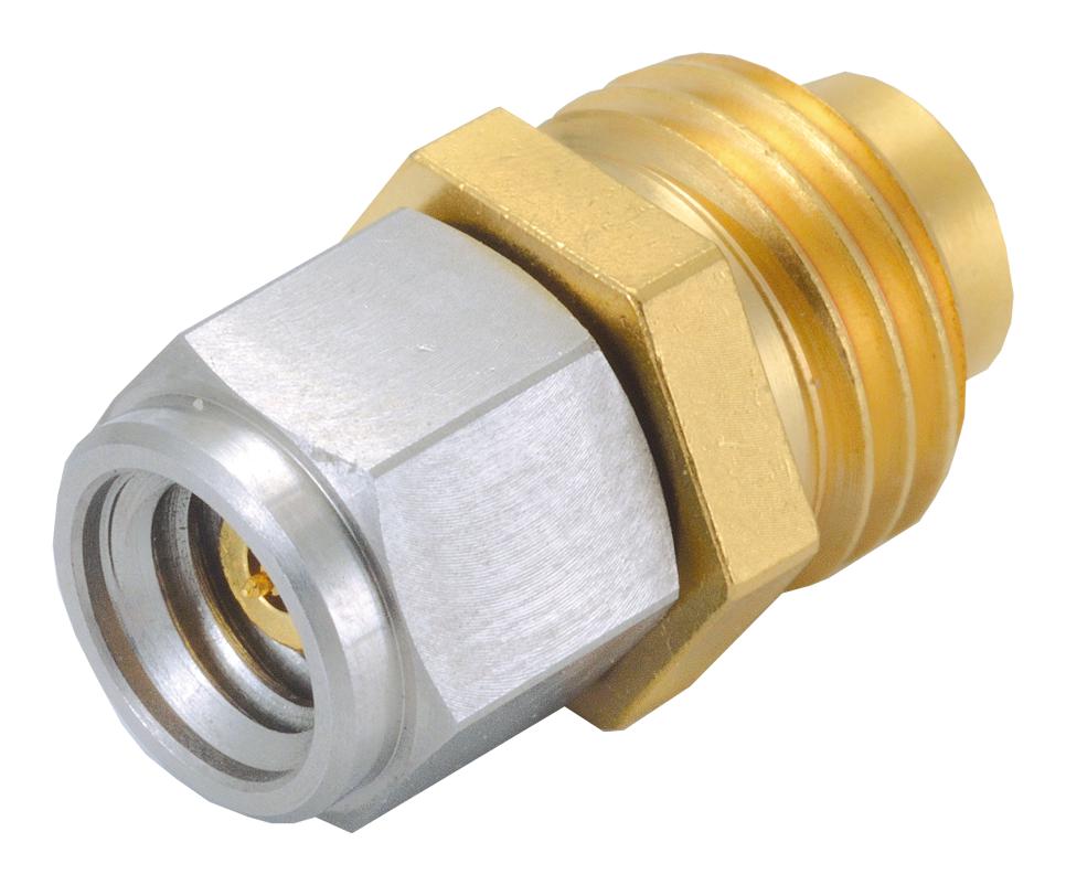 |
| Female Sparkplug | Male Sparkplug |
Adapters
|
||
 |
 |
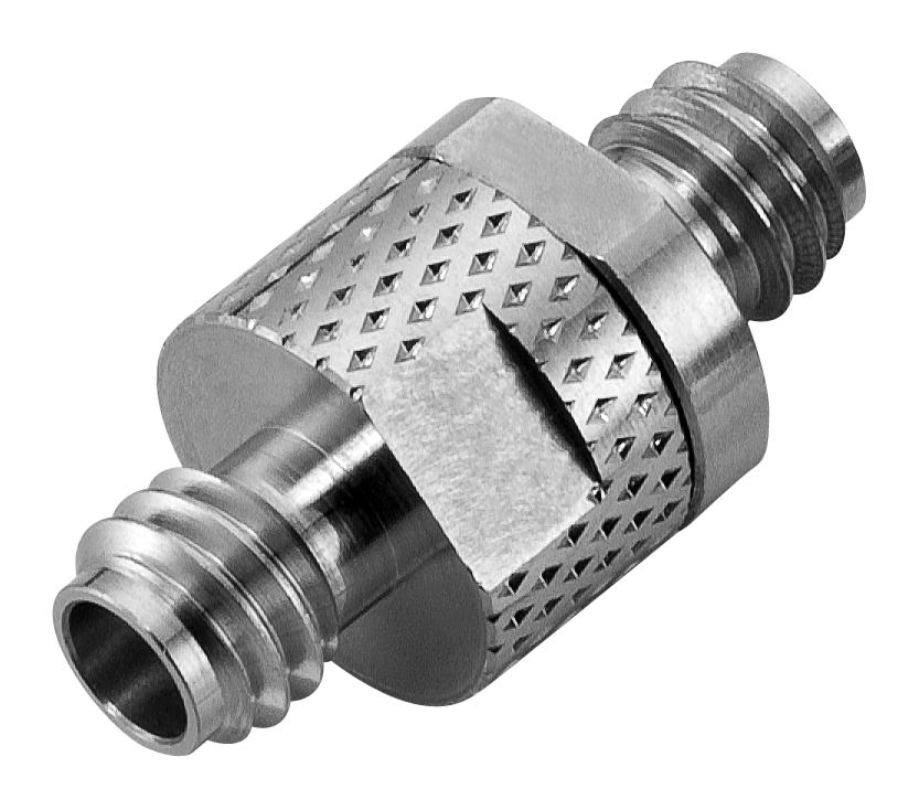 |
| Male to Male Adapter | Male to Female Adapter | Female to Female Adapter |
Looking to the Future
As technology advances, devices will start to use frequencies in the 100-200 GHz range. EHF bands over 100 GHz have several properties that differentiate them from lower frequencies, such as short propagation distances, large contiguous bandwidths, and physically small wavelengths. These characteristics make them suitable for applications such as:
High-capacity applications: EHF bands offer higher bandwidth for data transfer and communication. This could facilitate high bandwidth applications such as high-resolution 3D imaging.
Sensing applications: EHF bands propogate through materials in different ways than lower frequency bands. This could make them useful for detecting objects. Potential applications include finding material defects or health screenings.
Positioning applications: Because EHF bands have a high level of reflectivity, they are well suited for precise positioning applications, such as industrial robotics.
High density applications: The properties of EHF bands make them suitable for environments with a large number of wirelessly connected devices. Factories and offices are primary candidates, as well as smart city applications.
The 100 GHz to 3 THz range of frequency bands holds promise for the coming wave of wireless communication systems, due to the availability of broad swaths of unexplored and unused spectrum. The progression towards future-proof, wireless, high-capacity, cost-efficient backhaul networks will have a vital role in accommodating increased traffic demands, site location needs (including small and Pico cells), and the extension of future 5G services beyond 100GHz to raise 5G backhaul capacity.
Summing up – Connectors for mmWave Frequencies
Not too long ago, frequencies in the gigahertz range were considered science fiction; these days engineers are developing applications that are running at 100 GHz and more. mmWave and Sub-mmWave frequencies hold endless possibilities in industries like cellular, imaging, and automation, however, the EHF wavelengths have characteristics that present challenges in development and testing. As engineers explore frequencies higher on the spectrum, connectors, such as those from Cinch Connectivity Solutions, must be up to the task, providing reliable performance with low VSWR, insertion loss, and return loss.
