Take the Poll | Join our Discussion
sponsored by

Taming the Noise
Electromagnetic Interference (EMI) is an all-too-common issue, with unwanted signals originating from sources such as communication systems, medical equipment, and appliances. EMI can cause undesirable consequences, such as voltage fluctuations and noise in electronic devices. It can be generated by either artificial sources (televisions signal, switch-mode power supplies, and more) or natural sources (lightning, for example). Most electronic devices generate some amount of electromagnetic radiation; if the amount is large enough to affect the operation of another device, this is considered EMI. The threat of EMI can go beyond degraded performance; it can cause problems that have fatal consequences. There have been instances where emissions from cell phones have interfered with the function of critical medical equipment, to take an example. The exponential growth of wireless devices like Bluetooth, Wi-Fi, mobile phones, and near-field communication (NFC) has greatly increased the presence of EMI. This article focuses on the causes of EMI, their types, effects, and the prevention of them.
What Is Electromagnetic Interference?
As illustrated in Figure 1, electromagnetic interference consists of electromagnetic waves that are made up of both Electric (E) and Magnetic (H) field components, oscillating at a 90° angle to each other. EMI must be treated based on which field (E or H) is dominant; for example, materials with high permeability increase EMI attenuation for H-field components, while materials with high conductivity increase attenuation for E-field components. With modern electronics, the E-field is typically the dominant field in EMI.

Figure 1: Graphical representation of an Electromagnetic Wave
Source: Circuit Digest
What Are The Different Types of EMI?
In addition to being categorized as artificial or natural, EMI is also classified based on characteristics such as bandwidth, time duration, and EMI coupling mechanism.
Bandwidth
The types of EMI can be differentiated based on how much of the frequency range they affect. There are two types of EMI: Broadband and Narrowband.
Broadband EMI covers a great deal of the frequency spectrum, potentially distributing its energy over hundreds of megahertz. It can arise from both natural and artificial sources. Examples of man-made sources of broadband EMI include arcing or corona from power lines, communication transmitters, PCs, electric switch contacts, voltage regulators, and more. An example of a natural source of broadband EMI is a sun outage disrupting a communication satellite.
Narrowband EMI occupies a much smaller part of the frequency spectrum, often just a single interference frequency. This interference is typically observed as continuous sine waves, and can be continuous or intermittent. Narrowband EMI can be caused by communication transmitters, as well as oscillators or test equipment. Power line “hum” is a form of narrowband EMI, as well.
|
What is a sun outage? |
Duration
EMI is also categorized by its duration, whether constant or sporadic.
Continuous EMI is a constant interference. It can be emitted by a natural or artificial source, persisting as long as a coupling mechanism exists between the EMI source and the receiver.
Impulse noise is any unwanted signal, of natural or synthetic origin, that occurs either within a brief period or sporadically. Impulse noise can be caused by several sources, including lightning, electrostatic discharges, and current switching systems.
How Does EMI Get Into The Circuit?
There are several methods in which EMI gets from the source device to the receiver.
Radiation Coupling occurs when an unwanted signal is emitted from a source device through space, the strength of which is sufficient to disrupt the functionality of the receiver. Radiated EMI affects devices without physical contact.
Conduction Coupling occurs when unwanted signal or energy flows between two devices that are connected to each other. An example of conduction coupled EMI is noise on power supply lines.
Capacitive Coupling is caused when a changing voltage at the source device capacitively transfers an unwanted charge to another connected device.
Inductive/Magnetic Coupling occurs when a change in magnetic field between two nearby conductors (wires or cables) causes interference via electromagnetic induction.
Common-mode vs. Differential-mode Coupling
When EMI occurs via conduction coupling, it can take the form of differential mode or common mode currents. Differential-mode interference is energy that appears on two adjacent wires in a closed loop, where the current is flowing in opposite directions. This mode is distinct from common-mode inteference, which is a signal that appears in one or more wires where the current flows in the same direction, and then returns through a common path, such as a common ground, chassis, or radiation. Figure 2 illustrates Differential-mode (DM) and Common-mode signals (CM).

Figure 2: Differential Mode Signal (Green) and Common Mode Signal (Red)
Source: Interference Technology
Common-mode and differential-mode interference require different methods of filtering. Electrical circuits often generate both types simultaneously. Low frequency electrical noise is typical of differential-mode noise or currents, while high frequency noise tends to be common-mode.
How Do You Prevent EMI?
There are several methods to reduce or prevent EMI. Because EMI is dependent on environment, a combination of methods are used in most electrical devices.
Filtering
Filtering is an effective method of rejecting EMI. Passive filters are widely used in many devices; however, filters can also be active. Typically, devices use as the first line of defense an AC line filter to prevent dirty AC power from entering the power supply. AC line filters are usually dual-stage, with integrated differential mode and common mode filtering. Capacitors are used to bypass and decouple circuits. Additionally, 50 Hz or 60 Hz notch filters can also be used to eliminate AC hum. Figure 3 illustrates a typical EMI filter circuit, where Capacitor CX attenuates differential mode noise, signals, and spikes that appear from line to neutral, and Capacitor CY attenuates common-mode noise.
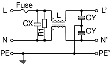
Figure 3: EMI Filter Circuit with X, Y capacitor and Inductor
Source: passive-components.eu
Shielding
Shielding is an effective method for reducing the amount of radiated EMI leaving or entering a cable or circuit. Shielding consists of using a physical barrier to block the radiated energy. Energy generated by the circuit is reflected back into the circuit or absorbed, while external radiated energy is blocked from entering. Common metals such as copper, steel, or aluminum are effective in shielding. Cables can be shielded using a standard conductive layer.
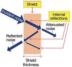
Figure 4: EMI Shielding
Source: Electrical4u
Grounding
Grounding is the establishment of a ground reference, along with an electrically conductive path to ground. Proper grounding protects the equipment from unwanted currents generated by faults and lightning. Improper grounding can cause EMI problems; an example would be a ground loop, where two devices that are supposed to have the same reference potential have different potentials. For some equipment, improper grounding can create a health hazard.


Figure 5: Series and Parallel EMI Grounding
Source: Electrical4u
Figure 5 illustrates two grounding methods, series and parallel, both utilizing a single-point ground. A parallel or “star” grounding connection, while being a more complex implementation, is preferred over a series connection because it leads to better rejection of ground loops and EMI. As shown in Figure 5, the ground potential of circuit 1 is affected by the return currents from circuit 2 and circuit 3. This is known as common-impedance coupling, and it can potentially lead to noise. Leads in a parallel grounding system should be as short as possible, and kept at the same or similar lengths; this avoids noise generation due to inductance or impedance differences.
Digital circuits are also well known for generating noise. A common practice is to have separate analog and digital grounds, and to combine them later at a single point.
Ohmite EMI Filters
Ohmite offers a wide range of EMI filters, including Inlet Filters Single Phase, Three Phase (3-Phase), Dual Stage, and PCB Filters. Ohmite EMI filters are UL and CSA-certified, and accommodate a variety of unique filter applications, such as electrical and electronic equipment, household equipment, power systems, and more.
AF Series
The AF series power entry modules are designed for 1A to 15A currents and up to 250 VAC single-phase circuits. They are available with dual fuses and dual throw switches for complete circuit protection. A standardized IEC plug fits all modules. The AF series filters feature fast-on terminations for quick and reliable connections. AF-A06-S and AF-B06-S are examples from this series.
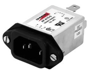
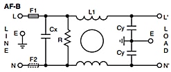
Figure 6: AF Series Filter with Internal Circuit
Source: Ohmite
AH Series
The AH series range of single-phase, double-stage filters is designed for low impedance load applications. This series filter controls continuous and intermittent interference noise in areas of high-level mains generated interference. They come in 1A to 100A ratings, and are available in 6 different case sizes, depending on current rating. AH-06 and AH-10 are some examples from this series.
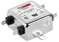

Figure 7: AH Series Filter with Internal Circuit
Source: Ohmite
AP Series - PCB - Single Stage - Through-Hole Filter
The AP series is designed for cost-effective filtering with concurrent space savings. Up to 6A current ratings and a max operating voltage of 250VAC make this series suitable for PLCs, electronic instruments, PC periphery, and other applications, where protection against interference voltage is required. AP-06 and AP-03 are some examples from this series.
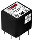
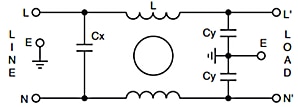
Figure 8: AP Series Filter with Internal Circuit
Source: Ohmite
Ohmite offers additional series of EMI filters, including AG, TG, and TK, with specifications that make them suitable for applications such as AC/DC drives, generators, wind turbines, SMPSs, and many more.
Summing up: How to Prevent EMI
Electromagnetic interference is a widespread problem in the design of electrical devices, the effects of which can cause disturbances such as power drops, transients, waveform distortions, voltage fluctuations, and amplitude and frequency variations. With the proliferation of electronic devices, as well as wireless technology, EMI prevention in the modern world is crucial. Various techniques can be employed to keep EMI at bay. Along with proper shielding and grounding, EMI filters are an effective solution for reducing or eliminating the effects of EMI.

Top Comments