A comparison of different types of oscilloscopes and an introduction to the mixed signal oscilloscope.
What are the Different Types of Oscilloscopes?
Oscilloscopes are diagnostic instruments that can be used to visualize and analyze the characteristics of electrical signals in real-time. They can be used to validate, test, debug, and verify circuit designs quickly and accurately while designing, manufacturing, or repairing electronic equipment. Analog and digital oscilloscopes are available, as well as mixed-signal oscilloscopes (MSO), which can display and compare both analog and digital signals. In this article, we will give an overview of the various features and advantages in using Tektronix mixed-signal oscilloscopes.
Oscilloscope Types and Architectures
Oscilloscopes can be categorized into analog and digital types. An analog oscilloscope captures and displays the voltage waveform in its original form. The screen of an analog oscilloscope displays signals using a cathode ray tube (CRT), producing a visible representation of an electrical signal that allows the user to observe the shape and behavior of the signal over time. In contrast, a digital oscilloscope uses a screen with a more modern technology, such as LCD. Digital oscilloscopes are preferred as they offer greater accuracy and precision, as well as being capable of storing and analyzing data.
A digital oscilloscope uses an analog-to-digital (A/D) converter to capture and store measured information digitally. The waveform is acquired as a series of samples, which are stored until a sufficient number are accumulated. The digital oscilloscope then reassembles the waveform for display on the screen. Additionally, digital oscilloscopes often have more advanced features, including the ability to trigger on specific events and to display multiple signals simultaneously. Many digital oscilloscopes also provide mean and RMS calculations, duty cycle, and other math operations. Digital oscilloscopes generally fall into five categories as explained below:
- Digital storage oscilloscope (DSO): DSO’s are suitable for low repetition rate or single-shot, high-speed, multichannel design applications.
- Digital phosphor oscilloscope (DPO): DPOs display Z-axis (intensity) measurements in real-time and are ideal troubleshooting tools for advanced analysis, communication mask testing, digital debugging of intermittent signals, repetitive digital design, and timing applications.
- Mixed signal oscilloscope (MSO): MSO’s help to quickly debug digital circuits using powerful digital triggering, high-resolution acquisition capability, and analysis tools.
- Mixed domain oscilloscope (MDO): MDO’s have the same capabilities as MSO’s and include an integrated spectrum analyzer that adds RF debugging to the analog and digital capabilities.
- Digital sampling oscilloscope: For very high-speed signal analysis, sampling oscilloscopes support jitter and noise analysis with ultra-low jitter acquisitions. They can achieve bandwidth and high-speed timing 10 times higher than other oscilloscopes for repetitive signals.
What is the Architecture of an Oscilloscope?
An oscilloscope can have either a serial-processing or parallel-processing architecture. Figure 1 illustrates how a DSO uses a serial-processing architecture to capture and display a signal. DSO’s process captured waveforms serially. The waveform capture rate is dependent on the speed of the oscilloscope’s microprocessor. DSO’s offer high performance in a single-shot, multichannel instrument.

Figure 1: Serial-processing architecture
DPOs use a parallel-processing architecture to process data. The DPO architecture dedicates unique ASIC hardware to acquiring waveform images, resulting in a higher signal visualization level. Figure 2 illustrates how a DPO’s microprocessor works in parallel with the integrated acquisition system for display management, instrument control, and measurement automation so that the oscilloscope’s acquisition speed remains unaffected. The direct rasterization of the waveform data removes the data-processing bottleneck.

Figure 2: Parallel-processing architecture
What is a Mixed Signal Oscilloscope?
A mixed signal oscilloscope (MSO) is a type of DSO that is capable of analyzing and troubleshooting analog and digital signals in a single instrument. An MSO has powerful digital triggering and high-resolution acquisition capability, as well as analysis tools that can help quickly debug digital circuits. These features allow you to view and analyze signals from multiple sources, providing a more comprehensive view of a system or circuit. Some of the key elements of MSO’s include advanced triggering capabilities for capturing and analyzing complex signal behavior, as well as protocol decoding, which allows the oscilloscope to automatically interpret and display standard serial protocols, such as I2C, SPI, and UART. High-resolution displays provide detailed and accurate views of the signals. Calculations can be performed on measured signals using built-in advanced math and analysis functions.
Oscilloscopes
Shop our wide variety of Oscilloscopes by Tektronix.
Don't forget to join our discussion.
Tektronix 2 Series MSO
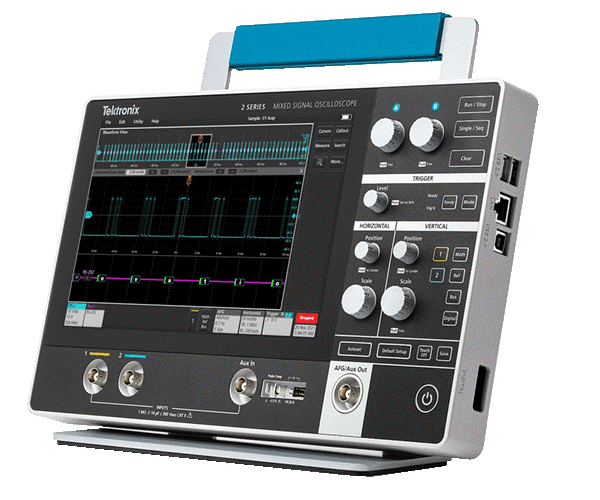
The 2 Series MSO is a full-featured, real-time touchscreen oscilloscope in a compact, portable form factor that feels like a tablet. The 2 Series MSO supports bandwidths up to 500 MHz with a maximum 2.5 GS/s sample rate. It has four analog and 16 digital channels, which can be synchronized and combined to display every characteristic of a signal.
Figure 3 illustrates the front and side of the 2 Series MSO. An optional detachable battery pack makes use on the bench or in the field more flexible. The 2 Series MSO features a 10.1-inch color touchscreen with an intuitive user interface that gives quick access to its functions. The touchscreen allows users to drag waveforms to pan and adjust position, as well as zooming in or out via pinch gestures. The 2 Series MSO can be connected to a network or directly to a PC or test equipment via onboard Ethernet port. It also includes USB 2.0 ports as well as an integrated digital voltmeter.

Figure 3: Tektronix 2 Series MSO
The 2 Series MSO includes an arbitrary function generator that supports a variety of preset waveform types, including sine, square, pulse, ramp, and triangle, as well as Gaussian, Lorentz, random noise, haversine, and cardiac. It also offers a complete set of advanced triggers, including edge, runt, logic, pulse width, timeout, rise/fall time, setup and hold, and parallel bus.
Table 1 mentions other essential specifications of the 2 Series MSO.
|
Features |
MSO22 |
MSO24 |
|
Analog channels |
2 |
4 |
|
Analog channel bandwidth |
70 MHz, 100 MHz, 200 MHz, 350 MHz, and 500 MHz |
|
|
Sample rate |
1.25 GS/s All channel, 2.5 GS/s half channels Interleaved |
|
|
Record length |
10 M |
|
|
Digital channels |
16 |
|
|
AFG outputs |
1 (multiplexed with Aux Out) |
|
|
Function Generator |
50 MHz, single channel with 128k point arbitrary waveform |
|
|
Protocol Analysis |
I2C, SPI, UART, CAN, CAN-FD, LIN, SENT |
|
Table 1: Features of 2 series MSO
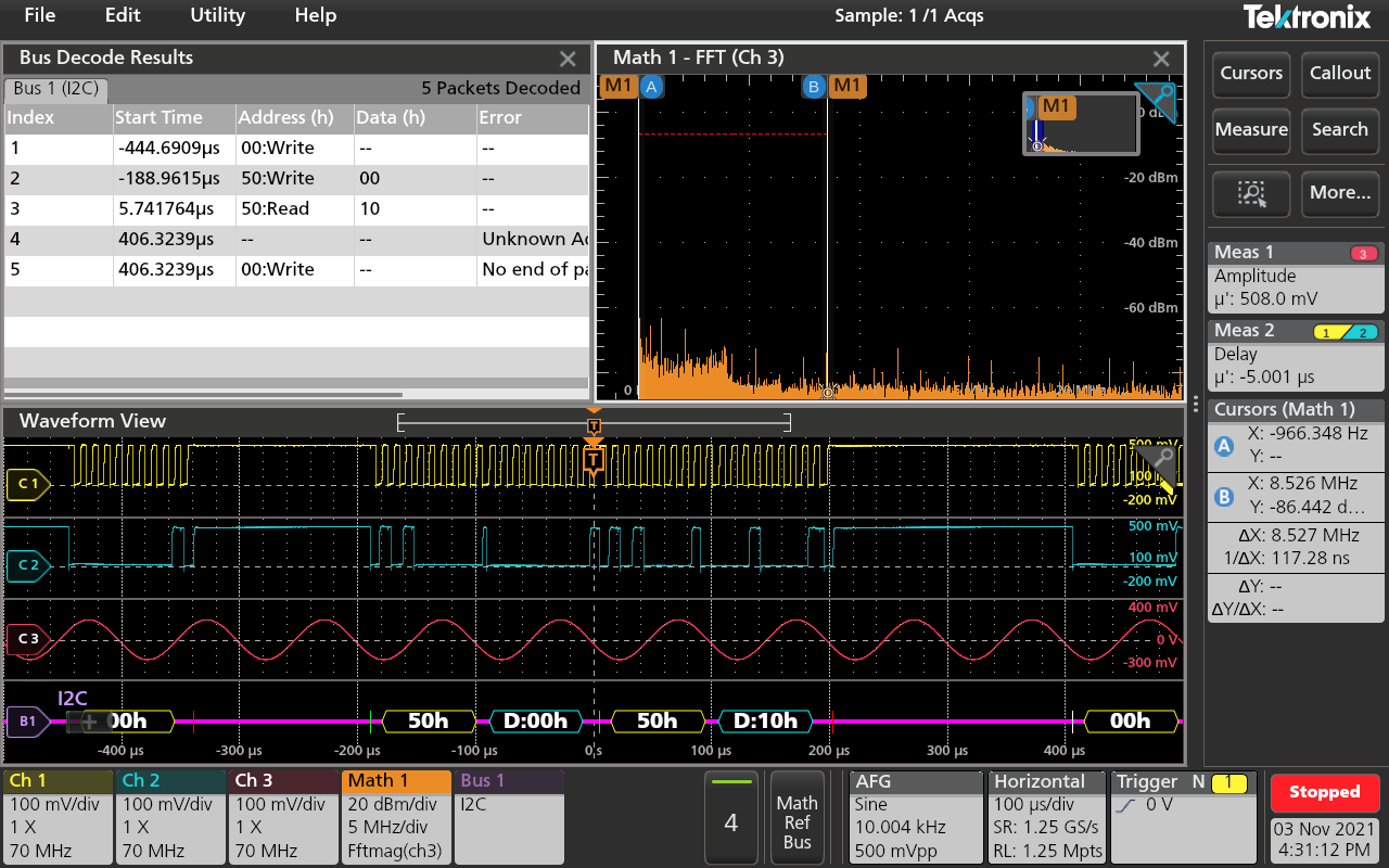
Figure 4 shows how the user interface can be customized to simultaneously view analog channels, math FFT plot, decoded serial bus waveforms, cursor readouts, results table, measurement results, and the setup information for each input. The various views can be relocated and resized as needed.

Figure 4: picture showing analog channels waveform view, decoded serial bus waveform
Any analog input can be a source for the voltmeter, using the same probes used for the oscilloscope. The frequency counter provides a precise readout of the frequency of the selected input channel. TekDrive and TekScope are natively integrated into the oscilloscope, allowing users to store, share, test, and analyze waveforms from any location.
Other MSO's by Tektronix
Tektronix offers several mixed-signal oscilloscopes with features such as multiple channels, color displays, and advanced triggering and analysis capabilities. The following table lists the MSO’s along with their differentiating features.
|
Series Model |
Bandwidth |
Record Length |
Channels |
Color Display |
|
6 Series B MSO |
1 GHz - 10 GHz |
62.5 M - 1 G |
4 analog |
15.6 in. |
|
8-32 digital (optional) |
(395 mm) |
|||
|
5 Series B MSO |
350 MHz - 2 GHz |
62.5 M - 500 M |
4–8 analog |
15.6 in. |
|
8-64 digital (optional) |
(395 mm) |
|||
|
4 Series MSO |
200 MHz - 1.5 GHz |
31.25 M - 62.5 M |
4, 6 analog |
13.3 in |
|
up to 48 digital (optional) |
(338 mm) |
|||
|
3 Series MDO |
100 MHz - 1 GHz |
10 M |
2, 4 analog |
11.6 inches |
|
16 digital (optional) |
(295 mm) |
|||
|
1 RF (optional) |
|
|||
|
2 Series MSO |
100 MHz - 200 MHz |
1 M |
2, 4 analog |
10.1 in. |
|
16 digital |
(180 mm) |
|||
|
MDO3000 Series |
100 MHz - 1 GHz |
10 M |
2, 4 analog |
9 in. |
|
16 digital (optional) |
(229 mm) |
|||
|
1 RF |
|
Table 2: Tektronix MSO/MDO
Summing up: Mixed-Signal Oscilloscopes
in partnership with

Mixed-signal oscilloscopes are capable of displaying and comparing both analog and digital signals. They feature all the benefits of a modern digital oscilloscope, including high-resolution display, touchscreen, and advanced triggers. The Tektronix 2 Series is a portable MSO that is equally at home on a bench as in the field. The 2 Series MSO features an intuitive interface and versatile connectivity options, as well as advanced debugging capabilities.
Oscilloscopes are very advanced these days. Do you remember the first oscilloscope you used and what you did with it?
Please tell us in the Comments section below.

-

gpolder
-
Cancel
-
Vote Up
0
Vote Down
-
-
Sign in to reply
-
More
-
Cancel
Comment-

gpolder
-
Cancel
-
Vote Up
0
Vote Down
-
-
Sign in to reply
-
More
-
Cancel
Children