

Have You Ever Wondered How Supercapacitors Work?
Supercapacitors are becoming popular as an energy source due to their very high capacitance, fast charge/discharge cycles, and power delivery capabilities. Supercapacitors are also known as electrochemical double layer capacitors (EDLCs) because the electrical charge is stored in the electric double layer that exists at the interface between its electrode (conducting material) and its electrolyte solution. In this article, we will discuss the benefits, construction, operation, and applications of supercapacitors.
Benefits of Supercapacitors
The primary benefits of a supercapacitor are listed below:
- Provide an excellent life span and can be cycled millions of times
- Able to operate over a wide temperature range from -40º C to +85º C
- Available in wide capacitance range (example, 0.047F, 10F and 3000-Farads)
- Up to 50 times higher power density as compared to batteries
- They are more efficient and environment-friendly than batteries
- Zero maintenance as compared to batteries
Let's Dig Deeper Into How Supercapacitors Work
An electrochemical double layer capacitor (or supercapacitor) consists of two electrodes narrowly separated by a dielectric material known as electrolyte. The electrode (plate) can be made up of carbon material such as activated carbon (AC), carbide-derived carbon (CDC), carbon aerogel, graphite (graphene), carbon fiber-cloth (AFC), graphene, or carbon nanotubes (CNTs). The electrolyte consists of solvent and dissolved chemicals that dissociate into cations (positive) and anions (negative). Electrolyte helps to make the ionic conductive connection between the two electrodes. Figure 1, shows the cross-sectional view of an electrochemical double layer capacitor / supercapacitor.
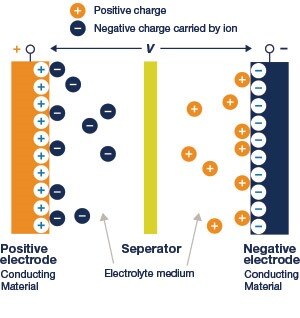
Figure 1: Cross-sectional view of an electrochemical double layer capacitor or supercapacitor
The properties of the EDLC depend on the electrode material and the type of electrolyte used. A separator is used to distinguish the two electrodes to prevent a short circuit by direct contact. It can be a very thin insulator made of carbon, paper, or plastic. Conducting materials are used to serve as the power connection between the electrode material and the external terminals of the supercapacitor.
Initially, there is no transfer of charge between electrode and electrolyte. When we apply a voltage to the conducting materials, both electrodes become polarized. The positively polarized electrode attracts the negative ions at the electrolyte; similarly, the negative polarized electrode attracts the positively charged holes. This process creates a double-layer, one on the positive electrode and other on the negative electrode. The insulator disturbs the natural pull of the negative charge towards the positive one, and the tension creates an electric field.
Unlike batteries, EDLCs can produce a fairly constant voltage. Once both plates are connected via an electronic load, electron flow starts, and current flows through the load. If the stored energy is not utilized, the internal resistance of the supercapacitor causes energy loss by diffusing ions in the electrolyte, which is called as self-discharge or leakage current. Leaking current effectively causes additional load on the capacitor causing it to discharge faster than expected. The discharging rate depends on capacitance, voltage, temperature, and the chemical stability of the electrode or electrolyte combination.
Charging or discharging an EDLC is related to the movement of charge carriers in the electrolyte. The internal resistance of a capacitor depends on the movement of charge carriers and increases with the increasing penetration depth of the charge carriers in electrodes. When both electrodes have approximately the same internal resistance, the potential of the capacitor will decreases symmetrically over both double-layers.
The capacitance is related to the Specific Surface Area (SSA) accessible by the electrolyte, its interfacial double-layer capacitance, and the electrode material density. The standard formula to calculate capacitance as follows:
C = εA/d
Where C is capacitance, ε is permittivity of the dielectric, A is area of the plates, and d is the distance between plates.
The supercapacitor's energy density is determined by the operating voltage and the specific capacitance of the electrode or electrolyte. The following formula is used to calculate the maximum energy stored in a capacitor (Wmax ) measured in Joules:
Wmax = 1/2 C V2
Where W = energy stored in Joules; C = capacitance (farad, F, µF); and V = potential difference (voltage).
The voltage range of supercapacitors is limited to a maximum of 5.5V and hence is highly suitable for embedded applications. Multiple supercapacitors can be connected in hybrid combinations (series-parallel) to obtain higher voltages (up to 62 volts) for use in high power equipment like and uninterruptible power supply or hybrid electric machines. Supercapacitors have a long operating lifetime with a nearly unlimited number of charge-discharge cycles. If maintained at a lower ambient temperature it can operate for about 10 years with a degradation factor of about 20%.
Supercapacitor Applications
Supercapacitors are a good fit for energy harvesting applications such as wind turbines, hybrid vehicles, backup power supplies, and solar arrays. In this section, let's explore some supercapacitor applications:
Backup power supply: A backup power supply is used to provide emergency power to a system when the primary source of power is disconnected. For example, embedded systems use back up power to allow the RTCs to maintain the operation of the clock and SRAM cells to preserve data for a planned time of failure. Figure 2 shows a schematic diagram of a backup power system.

Figure 2: Schematic diagram of a backup power system
The backup power supply is constructed using a supercapacitor, a charging circuit, a boost converter, and a Schottky diode. During normal operation, a supercapacitor charging circuit enables the charging of the backup supercapacitor. The boost converter helps to increase the voltage level to the load, which will drop in the event of main power failure. The boost converter helps to provide the required voltage to the load. During backup operation, the Schottky diode prevents the current flow from the boost converter to the main source.
Pulsed power system: Pulse power applications are characterized by a relatively low value of continuous current with small periods of high current requirements. Applications may need pulses that range from less than 1 msec to as high as a few seconds, and the pulse current can be orders of magnitude higher than the continuous or background current. The duty cycle of the pulses is usually low, typically less than 20%. A range of applications including phones, wireless modems, radio transceivers, motors, valves, and solenoids use short bursts of power. Figure 3, shows the schematic diagram of a supercapacitor based pulsed power system.

Figure 3: Schematic diagram of a pulsed power system
A pulsed power system is constructed using a charging circuit, a supercapacitor bank, and a switching device. The supercapacitor power bank has high energy density and is constructed using hybrid configurations of supercapacitors. A charging circuit is used to recharge the capacitor bank. A switch is used to allow the flow of electric power to a load during on time. As the load utilizes the stored energy, the output voltage will continuously decrease.
Hybrid vehicle power: In electric vehicles, the battery voltage may drop at various instances while running the BLDC motor. Subsystems like a power seat, power steering, power windows, and indicators may be affected due to this voltage drop. Supercapacitor modules are incorporated in hybrid electric vehicles to extend the life of batteries. Figure 4 shows the block diagram of a supercapacitor-based hybrid vehicle power system.

Figure 4: Block diagram of a hybrid vehicle power system
Hybrid vehicle power systems are constructed using supercapacitor stacks, DC/DC converter, Inverter, and BLDC motor. A DC/DC converter is used to draw a limited charge from the energy storage devices. The DC/DC converter is connected to supercapacitor stack allows bidirectional current flow that helps to store the regenerative braking voltage in the supercapacitors. An inverter circuit converts the DC voltage to an AC voltage and helps to drive the BLDC motor either in a clockwise or counter-clockwise direction.
| Coin Cell | Cylindrical Pack | 48V Rugged Module | 16V Supercapacitor Module |
|---|---|---|---|
KR Series Supercapacitors More InformationMore Information |
PM Series Supercapacitors More InformationMore Information |
XLR Series Supercapacitor Modules More InformationMore Information |
PowerStor XVM Series Supercapacitor Module More InformationMore Information |


Top Comments