

Communication protocols such as UART, SPI, and I2C provide an essential function in embedded systems. They function as an interface between a microcontroller and a peripheral to allow the devices to communicate with each other and the external world. The aim of this article is to make the reader familiar with the concepts of UART, SPI, and I2C and their usefulness.
What are communication protocols?
Other than controlling a motor or any other peripheral device, it is important that the devices possess mutual communication. A good example of such a scenario is a printer that sends a message to its connected computer when its printable paper stock gets exhausted. The devices must follow a specific set of rules or protocols to communicate. If one machine sends or receives data from another machine then both of them must use a similar protocol.
Modes of communication
Devices communicate by three modes:
• Simplex Mode: Communication in Simplex Mode is unidirectional. In this mode, one device only transmits while the other device only receives. Computer keyboards and monitors are prominent examples of Simplex Mode communication.
• Half-Duplex Mode: In half-duplex, the device can both send and receive data but not simultaneously. Here the entire capacity of the communication channel gets utilized for each direction. A walkie-talkie is an example of Half-Duplex mode of communication.
• Full-Duplex Mode: In full-duplex mode, both devices can simultaneously send and receive data. This occurs in two ways: either the channel gets divided for both the signals or it can utilize a separate transmission path. The telephone network is an example of Full-Duplex mode where both the caller and the receiver can talk and listen at the same time.
The most common and popular communication protocols in embedded systems are UART, SPI, and I2C. Let’s discuss each protocol in the following sections.
Universal Asynchronous Reception and Transmission (UART)
The acronym UART stands for Universal Asynchronous Receiver/Transmitter. It represents the hardware - integrated circuit and is used for serial communication via the serial port. UART is a standalone integrated circuit (IC) but can also be part of a microcontroller. It is capable of full duplex communication. A UART is relatively simple hardware and finds use when an inexpensive communication line is needed between devices. Since UART is peer to peer communication, it cannot incorporate multiple devices on the same bus.
UART Character Transmission: Figure 1 shows the timing diagram of a UART. Each block represents a single bit which can be a mark or space. Mark is logic high while space is logic low.
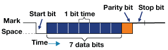
Figure 1: Timing Diagram of a UART
The bit travels with fixed time rate given in bits per seconds. This is known as the baud rate. The latter indicates how many times the lines can change state (high or low) per second. The most common baud rate is 9600 bits per second. The baud rate determines how fast data travels through the bus.
The transmission starts with the low bit which is seen by the receiver. It then sends out the data bits with the least significant bit first. The data bits can be 7 or 8 bits and are synchronized with the receiver. The 8th bit can be used by the receiver to check transmission error. It is also known as the parity bit. The parity can be even or odd. If the parity is set to be even and the sum of the number of 1’s in the data is even, then the parity bit gets set to zero. If the number of 1’s is odd then the parity bit is one. Similarly, if the parity is set to odd, and the number of 1's in the transmitted data is even, then the parity bit is set to zero. In any other condition, it is set to one.
Serial Peripheral interface (SPI)
The acronymn SPI stands for Serial peripheral interface. It is a synchronous full duplex serial data protocol. The SPI bus consists of four signals:
• MOSI – It is the signal generated by the master and received by the slave. Data sent from master to slave is usually sent with the most significant bit first.
• MISO - Miso is the signal generated by the slave although the flow of data is controlled by the master. The latter generates the clock-signal and gives it to the slave. The data sent from the slave back to the master is usually sent with the least significant bit first.
• SCK - It is the clock signal generated by the master used for synchronization of devices for data transfer.
• Chip select (CS) - This pin is used by the master to select a particular slave device.
SPI has one master and multiple slaves. The master can talk to any slave but only one slave at a time can talk to the master. Each slave has its own chip select signal.
The SPI bus Modes are of 4 types as shown in Table 1. This mode depends on the polarity (CPOL) and phase (CPHA) of the clock signal. CPOL provides the default value of the signal which can be either high or low, and CPHA gives the edge on which the clock data is sampled, i.e. the rising or falling edge.
| Mode | CPOL | CPHA |
|---|---|---|
| 0 | 0 | 0 |
| 1 | 0 | 1 |
| 2 | 1 | 0 |
| 3 | 1 | 1 |
Table 1: SPI mode definition
In mode 0, data transmission occurs at the leading or rising edge of the clock, where the clock polarity is low. In mode 1, data transmission occurs at the trailing or falling edge of the clock, where the clock polarity is low. In mode 2, data transmission occurs at the leading or falling edge of the clock, where the clock polarity is high. In mode 3, data transmission happens at trailing or rising edge of the clock, where the clock polarity is high. Figure 2 shows the SPI bus timing diagram.
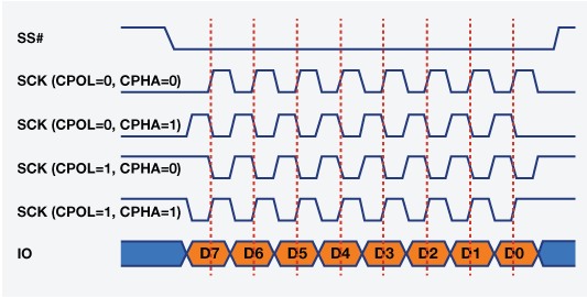
Figure 2: SPI bus timing diagram
Data transmission steps: The master configures the clock signal and output for due synchronization with slave devices. The master then makes the CS pin low to activate a particular device for communication. The master sends out the data bits through the MOSI line and slave read those bits. If the slave needs to send any data to the master, the latter will continue to generate clock cycles. The slave sends data to the master through the MISO line.
Inter-integrated-circuit (I2C)
I2C stands for Inter-Integrated Circuit and is a half-duplex protocol. The specialty of I2C is that it requires only two wires yet several devices can be connected. The I2C protocol has an acknowledgment feature, which can be used to ensure successful transmission of data. The size of the address used for the slaves is 7-bit or 10-bit. This means it is possible to connect 127 or 1023 devices. However, the number of devices which can be connected also depends on the capacitance of the bus and the distance.
Figure 3 shows the block diagram of the master and slave devices.
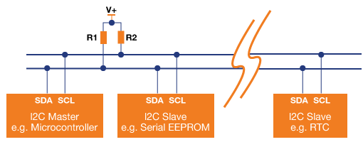
Figure 3: I2C: Block Diagram of the Master and Slave Devices
The Master are those nodes which generate a clock signal and initiate communication. The slave nodes receive the clock and responds to the master. In I2C, multiple masters and slaves can be connected. I2C uses open drain connections. The resistors shown in Figure 3 are pull up resistors that connect to the VCC lines.
Writing to the slave: The master starts communication by pulling the serial data (SDA) line low. The serial clock (SCL) line is kept high. Later the SCL goes low, signifying the start bit. The master then sends out the device address - 7-bit address. Only after that, it sends the write bit (R/W = 0). The slave device that matches this address sends out the acknowledgment bit. The master then sends out the address of the register in which it wants to write to. The slave sends the acknowledgment bit and the master then knows the slave is ready. The master sends the register data. It also sends the stop condition when data transfer is completed.
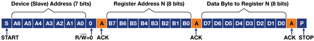
Figure 4: I2C: Writing to the slave
Reading From a Slave on the I2C Bus: The master starts the transmission. The first action of the master is to send the device address and the register address. This time, however, after receiving the acknowledgment bit it will again send a start bit instead of sending data byte to register. The master will then send out the 7-bit device address along with the read bit (R/W = 1). The slave will acknowledge the read request and the master will release the SDA line but continue to provide the clock pulse so that the slave can transmit the data. After every byte, the master will send out the acknowledgment bit so that the slave knows that the master is ready to accept more data. When the master receives the expected data, it will send out the NACK bit. The latter instructs the slave to stop the transmission and release the bus. The stop bit will be sent out at the final stage.
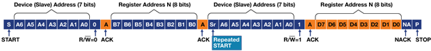
Figure 5: Reading From a Slave on the I2C Bus