


 Many people have heard of power budgets where an engineer sums up the power consumed by each part in a design under the different modes of operation to determine if there are any problems with power supplies or battery life (it is also a great double-check on an individual part's power consumption for thermal reasons). The same type of operation can be carried out on analog circuits to see if the sum of all part errors is too much for a design to reliably work.
Like the power budget, error budgets are used to give the designer some visibility into how a circuit will perform under different circumstances beyond what small-batch prototype testing can prove out. How can performance be guaranteed over the entire specification range promised by the part manufacturers? How does the unit operate at different temperatures? What happens to the circuits' accuracy over time? Clearly this type of calculation can become quite involved! However there are several situations where a solid error budget can be useful:
When a part goes obsolete, it can be difficult to determine if a slightly different part will cause the circuit to not work correctly in all situations. Having an error budget on hand will make this decision easier.
The error budget process is an excellent way to review a design even before a prototype is built.
It is a great troubleshooting tool, offering suggestions on parts that are major contributors to error and susceptible to manufacturing defects or counterfeit parts.
Error budgets are a source of exquisite documentation (in case the lead designer is hit by a bus, god forbid).
They are an excellent way to price out desired performance improvements. Marketing wants 1% better accuracy? No problem – according to the error budget one can use the selected, higher grade op-amp at an increased cost of $10 per unit.
Given all of these excellent uses for an error budget, why are they not used by analog hardware engineers everywhere? Well, they are time consuming, challenging, and involve a huge number of calculations done in Excel. They are also not always required as most circuits are not so sensitive and/or critical as to require this type of rigor in reviews. But in some cases a good error budget can make a big difference.
How does one create an error budget? The question that must be answered for each component is, “What error does this part create, and how does that error change the output?” An engineer can take this question to incredible depths, calculating the effect of many possible sources of error. However with experience (or guidance) the engineer can recognize components and specs that are most concerning and focus on those.
So let's jump right into a very simple example for the sake of discussion; an inverting op amp with a gain of -10:
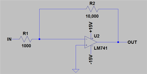
As any circuits book will write, the output of this circuit in the ideal case will be:
OUT = IN * (-R2/R1)
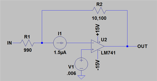
What else is going on when it is built in the real world? While there are many error sources associated with the LM741 op amp, we will just pick out a couple for this example and use 1% toleranced resistors. In order to save us from complicated statistics used by people who are very serious about their measurement uncertainty we will use worst-case figures from the datasheet. This will make the calculations much easier but the designer must remember that the result of our error budget will show the very unlikely case of all errors from all parts being at their worst spec at the same time.
Input Bias Current: 1.5uA, acting on a feedback resistance of 10kohms
(seen by the op amp as 15mV of input offset voltage error)
Input Offset Voltage: 6mV
Resistor Tolerance: 1%
How do these error sources appear in the schematic in their worst-case configuration? See the figure below with I1 being input bias current, V1 being Input Offset Voltage, and resistors adjusted in the worst way possible (1% each in opposite directions):
Now that we have identified the error sources we want to focus on, how can we calculate their impact on the output? There are two types of errors we will consider: offset and gain. An offset error changes the output by the same amount no matter what the input signal may be. In this -10x amplifier example, the input offset voltage is an offset error and will be the same at all input signal levels. A gain error, on the other hand, will cause a different error depending on the input signal. Here we see the resistor tolerance as a gain error since a 1% change in resistance will throw off the gain by 1%. If the input voltage is 0, there will be 0V of error from gain because 1% of 0 is still 0. However if the input signal is 1V, the gain will be 1% higher (i.e. -10.1x instead of -10x), casuing an error of 100mV at the output.
The best way to consider these errors together is to keep them in a table. Below is a table showing all effects of the errors pointed out above:
| Error | Offset | Gain |
| Input Bias Current | 15mV | |
| Input Offset Voltage | 6mV | |
| R1 Tolerance | 1.00% | |
| R2 Tolerance | 1.00% | |
| TOTAL ERROR | 21mV | 2.00% |
Based on these results, a designer could expect some significant errors! If the input was 1V with this worst-case situation, the output would be -10.221V instead of the desired -10V!
Of course this is a trivial example that is too simple to show the real power of error budgets as a design tool. A design with many stages of gain and error sources that are sensitive to time/temperature can quickly get complicated enough to require such a formal process. In these cases an error budget can be a true life (or job) saver!
For the interested reader who has been emboldened by this simple circuit a more complicated example can be found on page 12-16 of 'Op-Amps for Everyone' by TI where they discuss how error budgets can be used with ADC circuits. I can say from experience that an engineer can spend ages honing these error budgeting skills, and this is a great place to start!
-

gervasi
-
Cancel
-
Vote Up
0
Vote Down
-
-
Sign in to reply
-
More
-
Cancel
Comment-

gervasi
-
Cancel
-
Vote Up
0
Vote Down
-
-
Sign in to reply
-
More
-
Cancel
Children