


Like most engineers who have worked on PCB-level and system-level projects, I know from hard experience the ways noise can travel from one line to another. There are several unrelated ways for crosstalk to occur, so it's easy to think of it as black magic. At the EMC seminar I attended last week, I learned that there are only four paths for any signal, including crosstalk, to take. Having them enumerated allows you to work out the mechanism of crosstalk by process of elimination and then focus debugging efforts on the particular noise path at work.
1. Conducted Coupling (aka common impedance coupling) - Two currents share a conductor path whose resistance is not zero. The most common example of this is ground loops.

2. Inductive Coupling (aka mutual inductance coupling or H-field coupling) - Current in one line induces a current in another line, by the same means as in the windings of a transformer.
3. Capacitive Coupling (aka E-field coupling) - Two conductors close together form a capacitor allowing fast changes in voltage to flow from one conductor to the other.

4. Radiated Coupling (aka EM copuling, far-field coupling, plane wave) - An electromagnetic wave is radiated by one antenna and received on another antenna over a distance of greater than one wavelength.

This is an exhaustive list of the ways noise can travel. They are nothing new to an experienced PCB engineer, but having them in a clear list allows you to be methodical about eliminating noise. Here are some ideas about identifying each noise path:
Conductive Coupling: There must be two wires between the aggressor and victim. If there are no wires or only one wire between the source and victim, you can rule out conductive coupling.
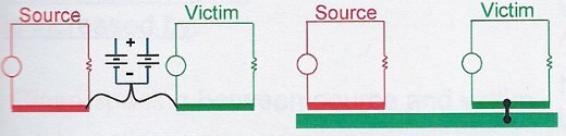
The above circuits cannot experience conductive coupling because there are not two conductors connecting them. .
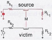
Inductive and Capacitive Coupling are similar. Inductive coupling causes current to flow in the opposite direction on the victim line, so if the victim load is on the same side as the aggressor load, the crosstalk noise voltage will be opposite of the aggressor current. The following example shows this property of inductive coupling.

A low-inductance ground path (in the case of a PCB, this is a solid plane with no gaps under the trace) will reduce inductive coupling into adjacent lines.
Radiated Coupling requires both the aggressor and victim have antennas. Antennas could be any piece two pieces of metal of size > wavelength / 4 with a voltage across them. A dipole antenna ideally consists of two pieces of metal exactly a quarter wavelength, but anything longer than that will radiate. If the wires are significantly shorter than a quarter wavelength, you can rule out radiated coupling. If the distance between the aggressor and victim is less than one wavelength, the coupling mechanism is not radiated.
All diagrams are from Lee Hill except for the inductive trace coupling diagram from Howard Johnson. Hill's seminar and Johnson's book are both excellent sources of information on this topic.