


Introduction
Raising a baby is tough enough as it is and the bathroom habits of an infant and impossible to predict. For some newborns, its viable to use disposable diapers however in most cases, the soft skin of the child is prone to rashes and the like with the use of harsh materials. When my son was born we were faced with a similar dilemma and as a result, we voted to employ cloth diapers. These are gentle to the skin however they tend to get wet once the child passes any fluid like material. This gets worse during the cold months and a consistent watch needs to be kept over the kid to ensure the change in nappy is as immediate as possible. This is the basis for my project titled “Anhad’s Nappy” which uses a low power micro controller to sense fluids and alert the caregivers of the situation.
In this blog post, the concept, design and implementation is discussed along with the demonstration and testing of the final prototype. This document presents the complete flow along with instructions for the readers who intend to replicate this project. The bill-of-materials, PCB gerbers, Oshpark project link and link to the github repository are provided under GPLv2 for anyone interested.
Detecting Liquids
There are a number of methods to measure the level and presence of liquids which can employ capacitive as well as inductive techniques. In this project, the simple resistive method of detection is employed wherein the presence of a liquid between two closely placed electrodes acts as a resistance of finite value. The theoretical resistivity of water is approximately 18.2Meg-cm which means for electrodes separated by 1cm of distance, the resistance measured will be 18.2Mega Ohms. For bodily fluids this resistance will be less than 1 Mega ohms and we can use this variation from infinity to finite value to sense the liquid.
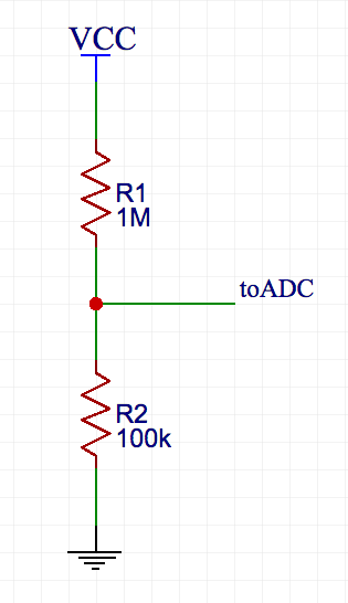
Figure 1: The Sensory Voltage Divider circuit
Figure 1 shows the sensory voltage divider circuit where R1 is the resistance due to the liquid and R2 is the balance resistor for creating the voltage divider. An alternative configuration may employ a wheatstone bridge however the additional two resistors are unnecessary. The operation of the circuit can be explained as follows.
The resistance R1 varies from infinity when dry and down to 1Meg when wet.
The output voltage variation can be calculated using Equation 1.
Vout = (Vcc-Gnd)xR2/(R1+R2) … Eq. 1
With no liquid, the resistance is infinity and the output voltage is zero and when the contact resistance is 1Mega Ohms, the output voltage is calculated to be 272.72mV. In order to make this value higher, R1 can be increased from 100k to a larger value however, in certain cases the value of R1 may be reduced further and the output voltages will be higher as well. For this project, the value of R2 was chosen to 100k and the results discussed are a result of this decision.
The Microcontroller
This voltage can be used in a multitude of ways including triggers to comparators and other analog circuits as well. However the objective of this exercise is to have a battery powered smart device and in order to make the design reusable and customisable, we shall employ a Microcontroller. In particular the Texas Instruments MSP430G2553 was used for a number of reasons listed as follows.
1. The MSP430 is cheap and available from a number of sources including TI.com, RSComponents and Element14
2. It has an inbuilt oscillator which reduces the BOM and complexity
3. It can operate at lower voltages ranging from 1.8V to 3.6V
4. The power consumed in the Low Power Modes is very small
5. Its available in the DIP Packaging for prototyping and TSSOP for final designs
6. It can be programmed using Energia which is the TI equivalent to the Arduino IDE which makes it easy to use.

Figure 2: The MSP430G Data-sheet/Feature List
The other features of the MSP430 are listed in the data sheet and Figure 2 shows an excerpt from the same.
Given a 10-bit ADC and a Vcc of 3V set as reference for the ADC, the resolution of the conversion is 3000mV/1024bits or 2.93mV/bit which means that for every 2.93mV change in ADC input, 1 bit will be the change in the final conversion. We shall discuss this further when we begin to customise the ADC Code and will use a different Vref than Vcc.
The Software Routine
The device is required to be in sleep mode most of the time to conserve battery life and will wake up every say 5 Minutes or 300 Seconds. This can be changed according to requirement but I feel its a good balance in frequency and power consumption. Once the device wakes up, it should start an ADC conversion and wait. This wait can be in sleep mode under ideal conditions however a awake wait may also work if the conversion speed is sufficient (To be discussed more later). Once the conversion is complete, the obtained value should be compared against a preset threshold and if the value is larger, a pre decided sequence of pulses should be sent to a pin on the controller which drives an LED. Once the operation is complete, it should go back to sleep.
In the above discussion, the predefined sequence of pulse cannot be created using analog circuits alone without increasing the BOM size. Figure 3 outlines the software routine and leaves place for further customisation.
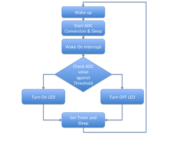
Figure 3: Flowchart for the software routine.
Testing the waters using a LaunchPad
The first prototype was made using a launchpad for testing the performance of the device. Short leads were connected to the analog pins and suspended in a container. Water was poured and the value of the ADC was monitored via the serial terminal using the example program in Energia.
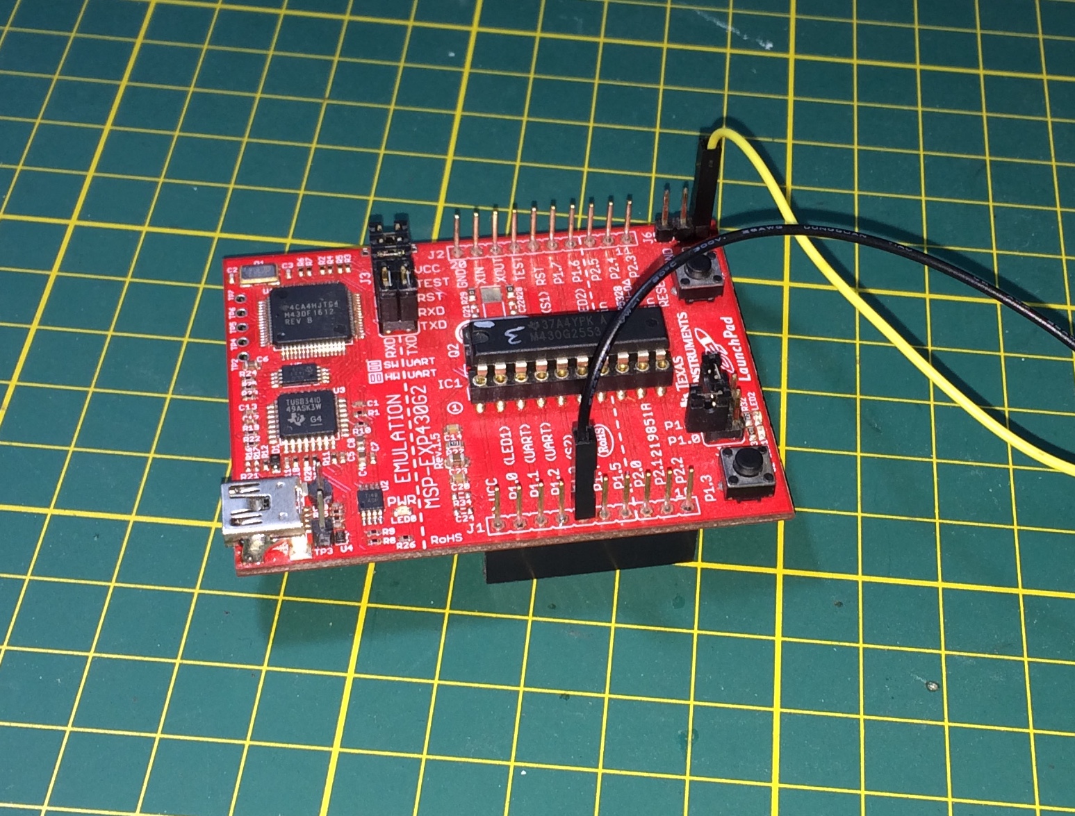
Figure 4: The test setup using the MSP430G2 Launchpad
It was seen that using tap water, the ADC varied from xxxxxxx to xxxxxx
This means that the value of threshold can be hard coded to a value of xxxxxx for comparison.
The final code will be made available on github and the link will be updated at the bottom of this post at a later date. Keep watching this space for updates.
Creating the PCB
A small general purpose PCB was cut and the components laid out and soldered manually. Since the MSP430 does not require an external crystal the circuit is quite simple and is shown in figure 5
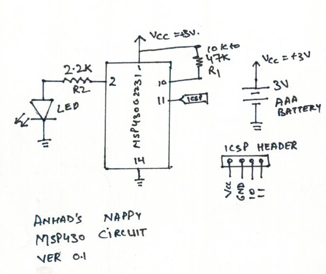
Figure 5: final circuit.
The LED is used for indication while an IR LED is used to signal a remote receiver. The code for that is to discussed I a different writing however the circuit is designed with the application under due consideration. The prepared PCB is shown in figure 6 and is powered using two AAA cells. The circuit is programmed using an MSP430 launchpad using the programming headers by using jumper cables.
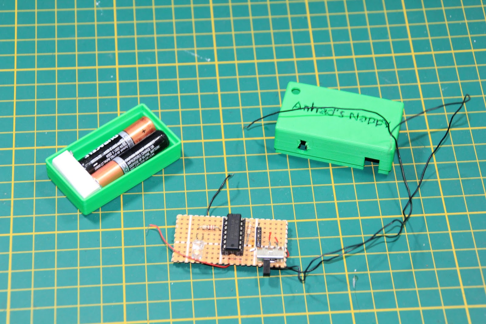
Figure 6: Final Circuit on General Purpose PCB
Enclosure
The final enclosure had to be custom made and in my case I designed it using Fusion 360. The same enclosure can also be designed using RS Design Spark Mechanical tool as well which is a very capable tool and is free for use unlike Fusion 360 which comes with a subscription model.
Figure 7 shows the final enclosure which also holds the AAA cells along with the PCB. The switch and LED are exposed to allow user interaction and the leads are fixed in place using super glue.
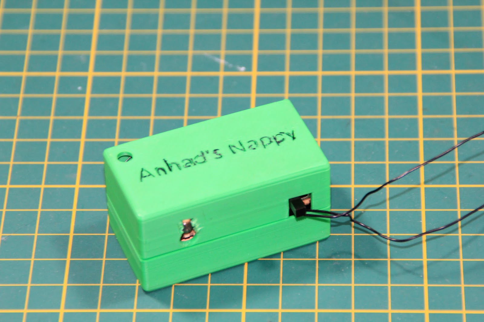
Figure 7: Final enclosure with top closed
Video
Conclusion
This was my attempt at solving a simple problem and it works. The idea was to have a small device that could last long on batteries and the MSP430 was selected for this very reason. Further analysis of the power consumption as well as the addition of the IR code is still experimental and is done using bit banging. I am still looking for a better way of doing this however since my son is much older now, this project has been shelved for now. A video description of the project is available at Youtube and to support me and such projects, please click the like button and subscribe to my channel.
Happy Hacking.
Top Comments
-

balearicdynamics
-
Cancel
-
Vote Up
+1
Vote Down
-
-
Sign in to reply
-
More
-
Cancel
-

ipv1
in reply to balearicdynamics
-
Cancel
-
Vote Up
+1
Vote Down
-
-
Sign in to reply
-
More
-
Cancel
-

balearicdynamics
in reply to ipv1
-
Cancel
-
Vote Up
0
Vote Down
-
-
Sign in to reply
-
More
-
Cancel
Comment-

balearicdynamics
in reply to ipv1
-
Cancel
-
Vote Up
0
Vote Down
-
-
Sign in to reply
-
More
-
Cancel
Children