element14 Community
element14 Community
    Register Log In
  • Site
  • Search
  • Log In Register
  • Community Hub
    Community Hub
    • What's New on element14
    • Feedback and Support
    • Benefits of Membership
    • Personal Blogs
    • Members Area
    • Achievement Levels
  • Learn
    Learn
    • Ask an Expert
    • eBooks
    • element14 presents
    • Learning Center
    • Tech Spotlight
    • STEM Academy
    • Webinars, Training and Events
    • Learning Groups
  • Technologies
    Technologies
    • 3D Printing
    • FPGA
    • Industrial Automation
    • Internet of Things
    • Power & Energy
    • Sensors
    • Technology Groups
  • Challenges & Projects
    Challenges & Projects
    • Design Challenges
    • element14 presents Projects
    • Project14
    • Arduino Projects
    • Raspberry Pi Projects
    • Project Groups
  • Products
    Products
    • Arduino
    • Avnet & Tria Boards Community
    • Dev Tools
    • Manufacturers
    • Multicomp Pro
    • Product Groups
    • Raspberry Pi
    • RoadTests & Reviews
  • About Us
    About the element14 Community
  • Store
    Store
    • Visit Your Store
    • Choose another store...
      • Europe
      •  Austria (German)
      •  Belgium (Dutch, French)
      •  Bulgaria (Bulgarian)
      •  Czech Republic (Czech)
      •  Denmark (Danish)
      •  Estonia (Estonian)
      •  Finland (Finnish)
      •  France (French)
      •  Germany (German)
      •  Hungary (Hungarian)
      •  Ireland
      •  Israel
      •  Italy (Italian)
      •  Latvia (Latvian)
      •  
      •  Lithuania (Lithuanian)
      •  Netherlands (Dutch)
      •  Norway (Norwegian)
      •  Poland (Polish)
      •  Portugal (Portuguese)
      •  Romania (Romanian)
      •  Russia (Russian)
      •  Slovakia (Slovak)
      •  Slovenia (Slovenian)
      •  Spain (Spanish)
      •  Sweden (Swedish)
      •  Switzerland(German, French)
      •  Turkey (Turkish)
      •  United Kingdom
      • Asia Pacific
      •  Australia
      •  China
      •  Hong Kong
      •  India
      •  Japan
      •  Korea (Korean)
      •  Malaysia
      •  New Zealand
      •  Philippines
      •  Singapore
      •  Taiwan
      •  Thailand (Thai)
      •  Vietnam
      • Americas
      •  Brazil (Portuguese)
      •  Canada
      •  Mexico (Spanish)
      •  United States
      Can't find the country/region you're looking for? Visit our export site or find a local distributor.
  • Translate
  • Profile
  • Settings
Community Hub
Community Hub
Member and Staff Blogs Experimenting with MOSFETS: Threshold Voltage
  • Blog
  • Forum
  • Documents
  • Quiz
  • Events
  • Leaderboard
  • Polls
  • Files
  • Members
  • Mentions
  • Sub-Groups
  • Tags
  • More
  • Cancel
  • New
Join Community Hub to participate - click to join for free!
  • Share
  • More
  • Cancel
Group Actions
  • Group RSS
  • More
  • Cancel
Engagement
  • Author Author: jc2048
  • Date Created: 15 Aug 2019 10:17 PM Date Created
  • Views 6866 views
  • Likes 14 likes
  • Comments 12 comments
  • mosfets
  • constant current
  • experimenting
  • op amp
  • threshold voltage
  • jc2048
Related
Recommended

Experimenting with MOSFETS: Threshold Voltage

jc2048
jc2048
15 Aug 2019


Previous blogs:


Experimenting with MOSFETS: Total Gate Charge

Experimenting with MOSFETs: Transfer Characteristic


Introduction


More experimenting with MOSFETs. In the last blog I looked at the transfer characteristics but it wasn't very easy to see from the graph I plotted where the threshold was. The threshold is measured at a drain current of 250uA and that is down in the noise for the current probe I was using. So this is a different approach to finding the threshold voltage.


Circuit


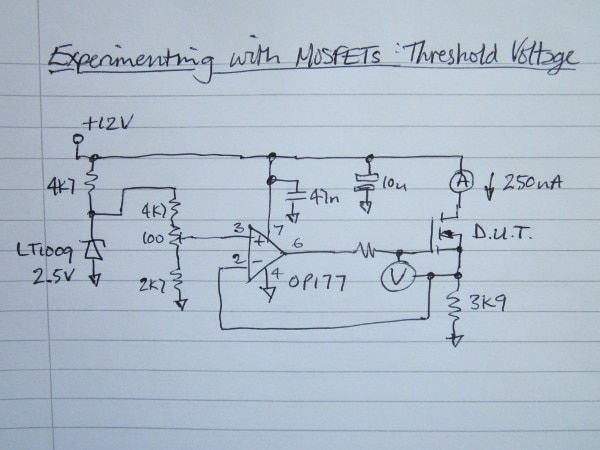
Here's the circuit I ended up with.


image


The current through the MOSFET is turned into a voltage by the source resistor. That gets compared to a voltage derived from a voltage reference and the op amp drives the gate in such a way as to make them match. Once I've adjusted it for 250uA flowing in the drain, the gate voltage (relative to the source) is the Vgs threshold voltage. [In case it's not obvious, I'm copying the constant-current load circuit that has been the subject of several blogs on the site here.]


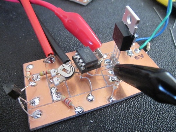
Here's the circuit built on a small piece of pcb material.


image


The op amp I used was an OP177. It's a precision op amp and maybe a bit 'over the top' for a simple experiment like this but it was close to hand. Although all the specs are for +-15V operation, it works fine for this on a single supply of 12V. The 47nF decoupling capacitor is underneath the package in case you're wondering why you can't see it. The gate resistor was simply being used to span the gap between the op amp output and the gate's pad on the board - it's not necessary for the operation. I used a 15 ohm resistor, but only because I had plenty (it's an odd value that I don't seem to design with much). The voltage reference I used was an LT1009. It's far too good for this but it was lying around on the bench so it got thrown into the pot. I didn't bother with any additional compensation for the op amp.


First Test


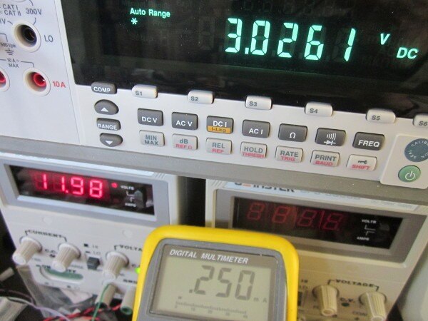
I set the current by adjusting the preset potentiometer whilst  looking at the drain current with a bench multimeter. Once I'd set it to 250uA, I got these readings for an IRL730 part - a threshold voltage of a fraction over 3V.


image


That's right in the middle of the range the manufacturer allows themselves in the datasheet


image


One thing I noticed a bit too late on in this is that their spec is measured for the case where the drain voltage is the same as the gate voltage. How much difference that makes I don't know. It might be simply to keep the dissipation down as the threshold voltage is temperature dependent.


More Tests


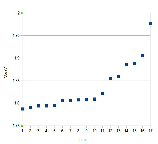
Having got this working, I thought I'd have a go at measuring a group of parts and see what the spread on them was. I don't have many IRL730 devices, but I did find an old tube with 17 STP55NF06LSTP55NF06L parts in it, so I tried those. The datasheet I've got gives a minimum of 1V and a typical of 1.7V (they are billed as being 'logic level' parts); it doesn't give a maximum figure.


This chart shows the Vgs for each of the 17 parts sorted by ascending voltage. Ten of the parts cluster around 1.8, the rest have values up towards 2V. Not quite as good as their typical value suggests but the spread is only 0.2V. Doesn't look like there's a very high chance of getting a 1V part.


image


If you found this interesting and would like to see more blogs I've written, a list can be found here: jc2048 Blog Index

  • Sign in to reply

Top Comments

  • jw0752
    jw0752 over 6 years ago +7
    Hi Jon, I decided to make a little more permanent test jig. I ended up using a TLE2142 OP amp since I didn't have an OP177. I also adjusted the 4k7 and the 2k7 in series with the pot so that i could use…
  • jc2048
    jc2048 over 6 years ago in reply to dougw +6
    I suspect it would need a much better test circuit. Even with just the 250uA, the reading isn't constant on my 5.5 digit multimeter as the device heats. For the group test, I took the measurements quickly…
  • jc2048
    jc2048 over 6 years ago +6
    When I saw in datasheets that the threshold voltage was normally measured with the drain voltage the same as the gate, I was curious about how much effect varying the Vds voltage would have on it. Simple…
  • cstanton
    cstanton over 6 years ago +5
    Huh, this's pretty good - thanks for the blog series
  • Jan Cumps
    Jan Cumps over 6 years ago in reply to jc2048 +5
    jc2048 wrote: ... I'm having fun with these blogs. ... +1
  • jc2048
    jc2048 over 6 years ago +5
    Here are two more. The STP55NF06L is a 'logic level' power device in a TO220 package, the BS170 is a 'small signal' device in a TO92 package. By coincidence, they had similar threshold voltages, so I put…
  • dougw
    dougw over 6 years ago +4
    Nicely done. I'd be interested to know if the gate voltage on these parts is more (or less) consistent with 100 mA through the source.
  • jw0752
    jw0752 over 6 years ago +4
    Hi Jon, I find this an interesting experiment and I hope to duplicate it on my bench. Thanks for the post. John
  • three-phase
    three-phase over 6 years ago +4
    Thanks for the informative blog, I too will try and set this up to carry out my own tests. Kind regards
  • clem57
    clem57 over 6 years ago +3
    Thanks jc2048 for me to learn about power MOSFETs.
  • dougw
    dougw over 6 years ago

    Nicely done. I'd be interested to know if the gate voltage on these parts is more (or less) consistent with 100 mA through the source.

    • Cancel
    • Vote Up +4 Vote Down
    • Sign in to reply
    • More
    • Cancel
  • cstanton
    cstanton over 6 years ago

    Huh, this's pretty good - thanks for the blog series image

    • Cancel
    • Vote Up +5 Vote Down
    • Sign in to reply
    • More
    • Cancel
<
element14 Community

element14 is the first online community specifically for engineers. Connect with your peers and get expert answers to your questions.

  • Members
  • Learn
  • Technologies
  • Challenges & Projects
  • Products
  • Store
  • About Us
  • Feedback & Support
  • FAQs
  • Terms of Use
  • Privacy Policy
  • Legal and Copyright Notices
  • Sitemap
  • Cookies

An Avnet Company © 2026 Premier Farnell Limited. All Rights Reserved.

Premier Farnell Ltd, registered in England and Wales (no 00876412), registered office: Farnell House, Forge Lane, Leeds LS12 2NE.

Follow element14

  • X
  • Facebook
  • linkedin
  • YouTube