


|
I'm messing about with a couple of old IC voltage regulator parts from a box of spare bits. Nothing very directed, just what takes my interest. This blog was inspired by Andrew posting this question Instrument Control Board - Prototyping the Power section
A regulator, of course, is a simple control system. In the case of these parts, the output voltage gets compared to an internal reference voltage [giving an error term] and a pass element then adjusts the current, with overall negative feedback acting to minimise the error. The circuit that does the comparison is effectively an operational amplifier and will behave in a similar way, though, unlike a discrete circuit on a breadboard on a bench, the fact that this is an IC with only three pins means that I don't have any easy way to probe what goes on inside. For all that, I might be able to deduce something of what it's doing from outside. I don't have the greatest test equipment that ever graced a lab, just a modest oscilloscope and an inexpensive Chinese waveform generator, but it should be enough to get some results, even if not all that precise.
LM7805
This one is the classic +5V regulator [perhaps I should donate it to a museum!]. I've started with this because I happen to know that it is stable with no capacitance on the output and that will help me see something of the way the control loop behaves.
The input is connected to a bench supply set to 9V and I've got the output connected to a load resistor to ground of 150 Ohms (that gives an output current of around 33mA). I've also attached the waveform generator, via a 50 ohm resistor and a 1500uF capacitor, so that I can drive the output with a signal and see what happens.
Here's how it behaves with a square wave. The blue trace is the regulator output. Each edge momentarily throws it and then the loop pulls it back to the 5V level. It takes about 8us to settle and looks reasonably well behaved.
So, what else can I do? Here's the result of throwing a sine wave at it.
This is at a couple of hundred kilohertz. The loop can't respond quickly enough to totally counter the change, though it does manage to attenuate it considerably.
The operational amplifier in the regulator, like many op amps, is internally 'compensated' to roll off its gain to ensure it doesn't give problems at high frequency, but that also has the side-effect of the effective output resistance of the part increasing as the frequency goes up. What I'm going to do is to measure at various frequencies and from those measurements calculate the output resistance. That, in turn, will give me an idea of how the open-loop gain varies with frequency. I can determine the resistance by measuring the amplitude at both ends of my 50 ohm resistor. Doing that will enable me to calculate the current through the resistor and I can use that, and the voltage directly at the output, to determine the approximate output resistance. If I was doing this properly, I'd also need to take into account the load resistor but, since the effective output resistance is unlikely to be more than 1% of the load resistor value, the very small error from not taking it into account will get lost in amongst all the other small errors.
Here's the graph I came up with:
Unfortunately, at the low end, the measurements were descending into the noise so I didn't go any further in that direction than you can see on the graph [perhaps I need to build myself a low-noise preamplifier for the 'scope]. From the graph we can see that the resistance [I probably ought to say impedance as the phase is moving too] is increasing by very roughly a factor of ten for each decade of frequency, so that suggests the gain is dropping by 20db per decade, which is very plausible if the compensation comes from a Miller capacitance. Unfortunately, because of the noise, I can't follow it down and find the frequency where the open-loop gain levels off at the DC value [if it's anything like the bipolar op amps of the time, that could be down at a few tens or hundreds of Hertz]. At the high end of the frequency scale we get a reversal which may, possibly, be to do with capacitive coupling between elements within the device affecting the response, but I'm just speculating there.
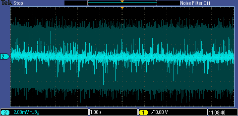
Noise
Whilst I had it on the bench I thought I'd look at the noise, but quickly decided I couldn't really do any sensible measurements with it set up like this. I'll show the sequence of traces out of interest.
This first is the 'scope noise with an old 50 Ohm terminator attached to the input connector. That's probably mostly the oscilloscope's vertical amplifier noise. The thermal noise from 50 ohms over 20MHz [566nV rms] is next to nothing in this context, and even with a few tens of uV of excess lf noise, depending on the composition of the resistor in the terminator [have I understood that right?], I don't think it's going to change what I see there much.
That's looking to be something like 2mV pk/pk, or 330uV rms if we assume a crest factor of 3.
Here it is, connected to the test board with a 1x probe [1M, no brand name, no idea what the tip C is], with no power to the circuit.
Loads of noise before I even start.
Here's the regulator with power on, but no output capacitors.
A noticeable increase in the noise.
This is with a 10uF electrolytic on the output
which has improved things quite a bit.
And, finally, with a 10uF electrolytic and a 47n ceramic
The sequence shows that the capacitors do certainly help reduce the noise, though I can't get any sensible numbers off of this.
After I'd done all that, I realised that, for the first step, I could just have switched the input channel on the 'scope to GND. Here's how that looks
Curiously, it's very much better than with the terminator [which is screened, by the way].
LM79M05
I also found an old LM79M05. By old, I mean really old: it's got a date code of 1977 on it. This is a negative voltage regulator for -5V. The M indicates that it can only manage 500mA, rather than the 1A of the standard part. Unfortunately, for reasons that I'll talk about in a moment, this device isn't stable without an output capacitor.
Here's how it behaves with no load resistor.
Instant oscillator, without even trying.
With a light load of 2k2 [2.3mA] it is stable, but only by the barest of margins: it does this with a square wave kicking the output.
'Ding, dong, the bells are going to chime.'
(We can see the ringing on the generator's square wave, too, because the generator has an internal 50 ohms in series with the output, for series-terminating the coax, so with my externally added 50R resistor there's actually a potential divider in play.)
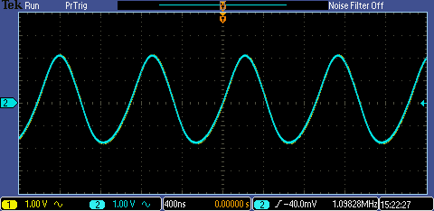
If I now change to a sinewave, this is the result
Entertaining, but not very useful for measurements.
Finally, here's the transient response with a 10uF electrolytic on the output and back to the 150R load.
That's doing fine.
I can't sensibly measure the way the output resistance [of the IC] behaves with frequency because I wouldn't be able to easily disentangle it from the way the output capacitor behaves (the equipment I'm using doesn't really allow for that degree of precision), so I'm going to leave the measurements there.
Why the difference in stability between the positive and negative regulator?
That becomes evident if we look at the equivalent internal circuits provided by ON Semiconductor in their datasheets for their 7805 and 7905 parts.
Here's the 7805. It's fairly straightforward. I've marked the pass element (A), and the differential pair (B) that compares the potted-down output voltage with the internal reference voltage, to help you orientate yourself if you're not used to discrete circuits.
The pass element is a pair of NPN transistors acting as emitter followers.
In the case of the 7905, we again have NPN transistors for the pass element, so this time the circuit that is being powered forms the collector load.
It isn't the 7805 circuit, with NPN swapped for PNP and vice versa, which you might expect.
Pease had this to say [1]: "The fixed negative regulators (LM320 family, LM7900 family) are likewise quite demanding that a decent capacitor be used for the output's damping. This is inherent because the negative regulators all have collector-loaded outputs, and you need a good capacitor to roll off the extra gain."
References
[1] Troubleshooting Analog Circuits. Robert Pease. Newnes. 1991.
If you found this interesting and would like to see more blogs I've written, a list can be found here:jc2048 Blog Index |


Top Comments