


dear engineers,
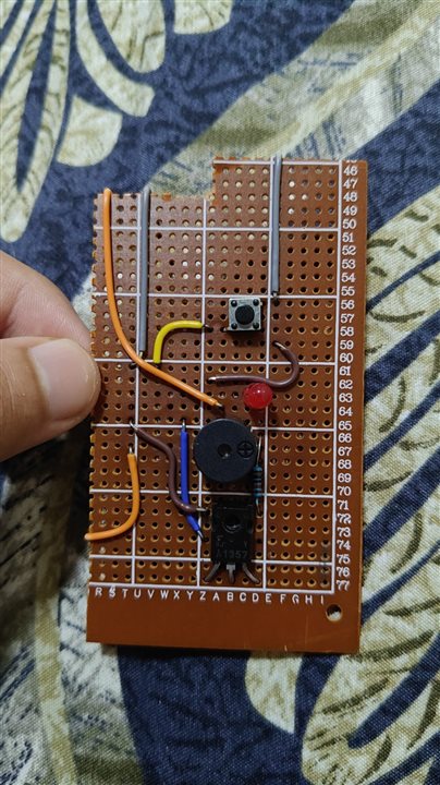
I am a 15-year-old starting out with PCB design. I recently designed a continuity tester circuit to check if a wire is properly connected or two pieces of wire are properly connected together. I built the circuit using an A1357 PNP transistor, a 10,000 Ω resistor, and some other components. The first picture shows my circuit schematics and the second picture shows the final version, now
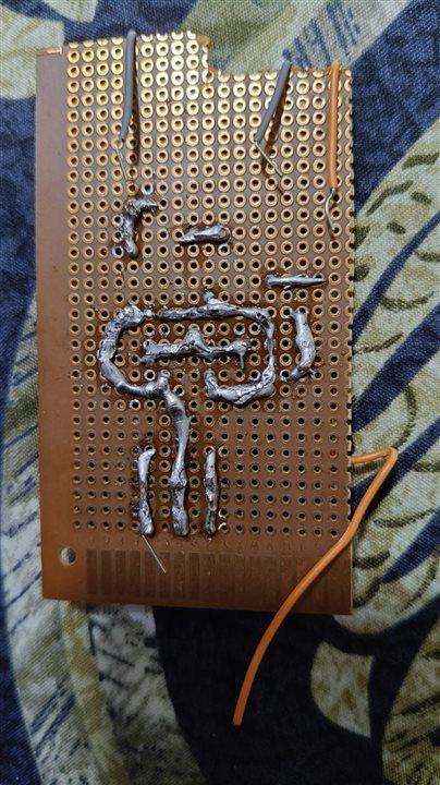
my circuit exactly follows the schematic and I checked it with another continuity tester. All the connections seem to be fine but the problem is that when I try to use the circuit, it does not work.
I have tried rewiring it and refreshing the solder in case there were any cold solder joints but it looks like my circuit wiring is fine. It could be an issue with the transistor since the transistor was very old. I want your help to figure out if there is something wrong with my schematics or if there can be another issue with it.
Your help will be highly appreciated,by a young hobbyist
now I know that I was supposed to put a resistor before the LED since I'm using 9 V but when making the circuit I completely forgot the resistor. That does not matter because my LED was in parallel with my buzzer. Even if the LED does not work, in parallel circuits the other component always works 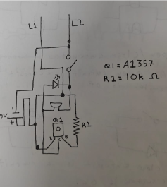
Top Comments
-

shabaz
-
Cancel
-
Vote Up
+1
Vote Down
-
-
Sign in to reply
-
More
-
Cancel
-

ezain
in reply to shabaz
-
Cancel
-
Vote Up
0
Vote Down
-
-
Sign in to reply
-
More
-
Cancel
Comment-

ezain
in reply to shabaz
-
Cancel
-
Vote Up
0
Vote Down
-
-
Sign in to reply
-
More
-
Cancel
Children