element14 Community
element14 Community
    Register Log In
  • Site
  • Search
  • Log In Register
  • Members
    Members
    • Benefits of Membership
    • Achievement Levels
    • Members Area
    • Personal Blogs
    • Feedback and Support
    • What's New on element14
  • Learn
    Learn
    • Learning Center
    • eBooks
    • STEM Academy
    • Webinars, Training and Events
    • Learning Groups
  • Technologies
    Technologies
    • 3D Printing
    • FPGA
    • Industrial Automation
    • Internet of Things
    • Power & Energy
    • Sensors
    • Technology Groups
  • Challenges & Projects
    Challenges & Projects
    • Design Challenges
    • element14 presents
    • Project14
    • Arduino Projects
    • Raspberry Pi Projects
    • Project Groups
  • Products
    Products
    • Arduino
    • Dev Tools
    • Manufacturers
    • Raspberry Pi
    • RoadTests & Reviews
    • Avnet Boards Community
    • Product Groups
  • Store
    Store
    • Visit Your Store
    • Choose Another Store
      • Europe
      •  Austria (German)
      •  Belgium (Dutch, French)
      •  Bulgaria (Bulgarian)
      •  Czech Republic (Czech)
      •  Denmark (Danish)
      •  Estonia (Estonian)
      •  Finland (Finnish)
      •  France (French)
      •  Germany (German)
      •  Hungary (Hungarian)
      •  Ireland
      •  Israel
      •  Italy (Italian)
      •  Latvia (Latvian)
      •  
      •  Lithuania (Lithuanian)
      •  Netherlands (Dutch)
      •  Norway (Norwegian)
      •  Poland (Polish)
      •  Portugal (Portuguese)
      •  Romania (Romanian)
      •  Russia (Russian)
      •  Slovakia (Slovak)
      •  Slovenia (Slovenian)
      •  Spain (Spanish)
      •  Sweden (Swedish)
      •  Switzerland(German, French)
      •  Turkey (Turkish)
      •  United Kingdom
      • Asia Pacific
      •  Australia
      •  China
      •  Hong Kong
      •  India
      •  Korea (Korean)
      •  Malaysia
      •  New Zealand
      •  Philippines
      •  Singapore
      •  Taiwan
      •  Thailand (Thai)
      • Americas
      •  Brazil (Portuguese)
      •  Canada
      •  Mexico (Spanish)
      •  United States
      Can't find the country/region you're looking for? Visit our export site or find a local distributor.
  • Translate
  • Profile
Members
Members
Blog [jc2048] Staircase Generator
  • Blog
  • Forum
  • Documents
  • Events
  • Leaderboard
  • Members
  • Mentions
  • Sub-Groups
  • Tags
  • More
  • Cancel
  • New
Members requires membership for participation - click to join
Blog Post Actions
  • Subscribe by email
  • More
  • Cancel
  • Share
  • Subscribe by email
  • More
  • Cancel
Group Actions
  • Group RSS
  • More
  • Cancel
Engagement
  • Author Author: jc2048
  • Date Created: 27 Nov 2021 4:14 PM Date Created
  • Views 1953 views
  • Likes 11 likes
  • Comments 23 comments
  • intel
  • MAX II
  • cpld
  • experimenting
  • analogue design
  • vhdl
  • transistors
  • jc2048
  • altera
Related
Recommended

[jc2048] Staircase Generator

jc2048
jc2048
27 Nov 2021

Introduction

Here's a curious waveform. How do you think I did that?

image

At first glance it looks like the output of a DAC driven from an incrementing counter, but it's not.
Instead, I have a digital part (a CPLD), producing a simple stream of pulses, and an analogue part
that works as a 'charge pump', adding a set amount of charge to a capacitor each time one of the
control pulses arrives. There's also a reset pulse to bring the level back down close to zero.

Here's the waveform again with the control pulses from the CPLD below it.

image

The output changes in response to the pulses, so it is 'discrete time' in nature [like sampling], and
the steps are a fixed size [so like the quantization of digitising], yet the core of it is analogue
with not a gate in sight. Another way of thinking about it, is that it's a kind of analogue adder.

This is the circuit diagram of the analogue part that I drew before construction. The build was
similar, except that I added a 15R resistor between the MOSFET and the 68n.

image

When the 'step' transistor is off, the 2.2n capacitor charges via the 1k resistors to each rail. When
the transistor turns on, it lifts that end of the capacitor to the rail and the other end lifts above
the rail, turning on the second transistor and allowing the 2.2n capacitor to discharge into the 68n.
When the 'reset' waveform goes high, the MOSFET simply discharges the 68n capacitor. Obviously,
whatever is connected to the 68n capacitor needs to be a fairly high impedance or the capacitor will
just discharge via the load - the 10M 'scope probe suffices for the experiment.

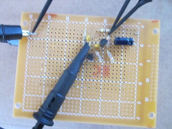
This is the build on a little prototyping board [the MAX II CPLD board is underneath - it's not very
obvious, but there are headers going down to it].

image


CPLD Logic Design

Here is the VHDL that produces the 'step' and 'reset' waveforms. It's fairly straightforward. I chose
a basic timing interval of 10us [it doesn't want to be too fast or the capacitors won't charge and
discharge fully], so I have a prescaler that produces an enable for one clock every 10us and work from
there with a simple state machine, with three states, and a counter to count off the steps to give the
two waveforms. (Sorry I haven't quite got the hang of using _numeric and I'm still overloading the
addition with ieee.std_logic_unsigned)

---------------------------------------------------------------
--- Filename: CPLD-staircase-generator.vhd                  ---
--- Target device: EPM240T100C5                             ---
---                                                         ---
--- control pulses for analogue staircase generator         ---
---                                                         ---
--- Jon Clift 7th November 2021                             ---
---                                                         ---
---------------------------------------------------------------
--- Rev    Date         Comments                            ---
--- 1.0    07-Nov-21                                        ---
---------------------------------------------------------------

library IEEE;
use IEEE.std_logic_1164.all;  
use ieee.std_logic_arith.all;
use ieee.std_logic_unsigned.all;
  
entity CPLD_staircase_generator is  
  port (  
    clk_i:       in  std_logic;      --- input clock (50MHz osc).  
    step_x:      out std_logic;      --- 
    reset_x:     out std_logic       --- 
    );  
end CPLD_staircase_generator;  
  
architecture arch of CPLD_staircase_generator is

constant STEP_X_STATE : std_logic_vector(1 downto 0) := "10";
constant PAUSE_X_STATE : std_logic_vector(1 downto 0) := "01";
constant RESET_X_STATE : std_logic_vector(1 downto 0) := "00";
constant NUMBER_OF_STEPS : std_logic_vector  (3 downto 0):= "1001";  --- 9 steps
constant STEP_INTERVAL : std_logic_vector  (3 downto 0):= "1001";    --- 9 (x 10us) between step pulses  
signal ten_micro_en: std_logic;  
signal prescaler: std_logic_vector (8 downto 0) := "000000000";   
signal interval_count: std_logic_vector (3 downto 0) := "0000";
signal step_count: std_logic_vector (3 downto 0) := "0000";
signal state: std_logic_vector (1 downto 0) := RESET_X_STATE;

begin

   clocked_stuff: process (clk_i)
      begin
         if (clk_i'event and clk_i='1') then

            --- prescaler down to 10us period
          
            if (prescaler(8 downto 0) = "111110011") then   --- if reached 499
               prescaler(8 downto 0) <= "000000000";        --- reset back to zero
               ten_micro_en <= '1';                         --- and set enable for one cycle
            else                                            --- else count down
               prescaler <= prescaler + 1;
               ten_micro_en <= '0';                         --- keeping enable low rest of time
            end if;

            --- state machine to generate the waveforms
         
            if (ten_micro_en = '1') then
               case state is
                  when STEP_X_STATE =>
                     step_x <= '0';
                     reset_x <= '0';
                     interval_count <= STEP_INTERVAL;
                     state <= PAUSE_X_STATE;
                  when PAUSE_X_STATE =>
                     step_x <= '1';
                     reset_x <= '0';
                     if(interval_count = "0000") then
                        if(step_count = "0000") then
                           state <= RESET_X_STATE;
                        else
                           step_count <= step_count - 1;
                           state <= STEP_X_STATE;
                        end if;
                     else
                        interval_count <= interval_count - 1;
                     end if;
                  when RESET_X_STATE =>
                     step_x <= '1';
                     reset_x <= '1';
                     interval_count <= STEP_INTERVAL;
                     step_count <= NUMBER_OF_STEPS;
                     state <= PAUSE_X_STATE;
                  when others =>
                     state <= RESET_X_STATE;
                  end case;
            end if;
            
         end if;
      end process;
 
end arch;  

Inspiration

If you are interested in what my inspiration for this was, it came from this booklet published by the
British electronics company Ferranti in the mid-seventies (you can tell it's the 1970s by the groovy
fonts without capitals and the glorious orange colour: designers back in the 1960s and 1970s had a lot
of fun before the world got all corporate, safe, and bland again) to promote their E-line transistors
(ZTX... series parts, still in production, though now owned by Diodes Inc as Ferranti is long gone).

image


This was their version of the circuit

image


I turned it upside down and added the CPLD to generate the pulse stream, but other than that it's much
the same, with just a little tweaking of values.

One difference, though, is that their circuit self-resets when the capacitor voltage reaches a preset voltage.

I don't imagine there's anything you might use it for now that couldn't be done better in other ways,
but it was fun to experiment with, and switched-capacitor circuits are still relevant in some areas.

If you found this blog interesting, you might like to read some of the others I've written: jc2048-blog-index-new-version

References

[1] Application Report: E-Line Transistors. Ferranti. 1975.

  • Sign in to reply

Top Comments

  • genebren
    genebren over 1 year ago +2
    Very cool project/blog! I really like the simplicity/elegance of your approach to this project. Nice example of using a CPLD to generate a programmable pulse sequence. Well done!
  • DAB
    DAB over 1 year ago +2
    It has been a long while since I did any transistor work. Well done.
  • Jan Cumps
    Jan Cumps over 1 year ago +2
    The FPGA design works like a charm. Running it on Xilinx Zynq. Clock also 50 MHz.
  • Pelorito1993
    Pelorito1993 6 months ago

    The circuit is extremely simple and inexpensive compared to ladder generators made with binary counters and gates. It may not have a lot of precision but in some applications precision is not so necessary.
    It could be used to plot semiconductor characteristics as the old Tektronix 370 did.
    Each step jump could be an "Ib" of a transistor for example.
    I think the development would be more complete if you included two important things.
    a) The possibility to determine the number of steps you want. For example, you could place a reference voltage and a comparator. When the ladder reaches that reference voltage, it triggers a pulse that resets the ladder making it start again.
    If you can make the height of each step equal to the input voltage, you could even have an analog counter.
    If you know that your input voltage is - for example - 100 mV, and you set your reset voltage to 10 Volts, then you know that if the ladder has reset it means that 100 steps were generated. To achieve this, you need the height of each step to be exactly at the voltage you set at the input. This way you would have a tension variable staircase. (voltage Variable Staircase or VVS)
    This so designed can be used to make a step generator where with a key you can choose how many steps you want the signal to have .....
    These are all ideas that can be developed.
    A friendly greeting from Argentina

    • Cancel
    • Vote Up 0 Vote Down
    • Sign in to reply
    • More
    • Cancel
  • Jan Cumps
    Jan Cumps over 1 year ago in reply to Jan Cumps

    1. Slice Logic
    --------------
    
    +-------------------------+------+-------+-----------+-------+
    |        Site Type        | Used | Fixed | Available | Util% |
    +-------------------------+------+-------+-----------+-------+
    | Slice LUTs              |   19 |     0 |     53200 |  0.04 |
    |   LUT as Logic          |   19 |     0 |     53200 |  0.04 |
    |   LUT as Memory         |    0 |     0 |     17400 |  0.00 |
    | Slice Registers         |   22 |     0 |    106400 |  0.02 |
    |   Register as Flip Flop |   22 |     0 |    106400 |  0.02 |
    |   Register as Latch     |    0 |     0 |    106400 |  0.00 |
    | F7 Muxes                |    0 |     0 |     26600 |  0.00 |
    | F8 Muxes                |    0 |     0 |     13300 |  0.00 |
    +-------------------------+------+-------+-----------+-------+
    

    2. Slice Logic Distribution
    ---------------------------
    
    +--------------------------------------------+------+-------+-----------+-------+
    |                  Site Type                 | Used | Fixed | Available | Util% |
    +--------------------------------------------+------+-------+-----------+-------+
    | Slice                                      |    6 |     0 |     13300 |  0.05 |
    |   SLICEL                                   |    3 |     0 |           |       |
    |   SLICEM                                   |    3 |     0 |           |       |
    | LUT as Logic                               |   19 |     0 |     53200 |  0.04 |
    |   using O5 output only                     |    0 |       |           |       |
    |   using O6 output only                     |    9 |       |           |       |
    |   using O5 and O6                          |   10 |       |           |       |
    | LUT as Memory                              |    0 |     0 |     17400 |  0.00 |
    |   LUT as Distributed RAM                   |    0 |     0 |           |       |
    |   LUT as Shift Register                    |    0 |     0 |           |       |
    | Slice Registers                            |   22 |     0 |    106400 |  0.02 |
    |   Register driven from within the Slice    |   20 |       |           |       |
    |   Register driven from outside the Slice   |    2 |       |           |       |
    |     LUT in front of the register is unused |    0 |       |           |       |
    |     LUT in front of the register is used   |    2 |       |           |       |
    | Unique Control Sets                        |    4 |       |     13300 |  0.03 |
    +--------------------------------------------+------+-------+-----------+-------+

    • Cancel
    • Vote Up 0 Vote Down
    • Sign in to reply
    • More
    • Cancel
  • Jan Cumps
    Jan Cumps over 1 year ago in reply to Jan Cumps

    8. Primitives
    -------------
    
    +----------+------+----------------------+
    | Ref Name | Used |  Functional Category |
    +----------+------+----------------------+
    | BIBUF    |  130 |                   IO |
    | FDRE     |   22 |         Flop & Latch |
    | LUT4     |   10 |                  LUT |
    | LUT5     |    7 |                  LUT |
    | LUT6     |    4 |                  LUT |
    | LUT3     |    4 |                  LUT |
    | LUT2     |    3 |                  LUT |
    | OBUF     |    2 |                   IO |
    | PS7      |    1 | Specialized Resource |
    | LUT1     |    1 |                  LUT |
    | BUFG     |    1 |                Clock |
    +----------+------+----------------------+

    • Cancel
    • Vote Up 0 Vote Down
    • Sign in to reply
    • More
    • Cancel
  • Jan Cumps
    Jan Cumps over 1 year ago in reply to jc2048

    Here's the summary:

    image

    I had to place the Processing System (ARM) on the design.
    It's mandatory, I don't know how much traditional resources it uses, but I expect it's going to be virtually nothing in this design.
    I used it to serve the clock.

    • Cancel
    • Vote Up 0 Vote Down
    • Sign in to reply
    • More
    • Cancel
  • dougw
    dougw over 1 year ago

    Your circuit would also lent itself to making a smooth sawtooth wave by using a small pump cap (small step size) and a lot of steps.

    Pretty versatile circuit.

    • Cancel
    • Vote Up 0 Vote Down
    • Sign in to reply
    • More
    • Cancel
>
element14 Community

element14 is the first online community specifically for engineers. Connect with your peers and get expert answers to your questions.

  • Members
  • Learn
  • Technologies
  • Challenges & Projects
  • Products
  • Store
  • About Us
  • Feedback & Support
  • FAQs
  • Terms of Use
  • Privacy Policy
  • Legal and Copyright Notices
  • Sitemap
  • Cookies

An Avnet Company © 2023 Premier Farnell Limited. All Rights Reserved.

Premier Farnell Ltd, registered in England and Wales (no 00876412), registered office: Farnell House, Forge Lane, Leeds LS12 2NE.

ICP 备案号 10220084.

Follow element14

  • Facebook
  • Twitter
  • linkedin
  • YouTube