element14 Community
element14 Community
    Register Log In
  • Site
  • Search
  • Log In Register
  • About Us
  • Community Hub
    Community Hub
    • What's New on element14
    • Feedback and Support
    • Benefits of Membership
    • Personal Blogs
    • Members Area
    • Achievement Levels
  • Learn
    Learn
    • Ask an Expert
    • eBooks
    • element14 presents
    • Learning Center
    • Tech Spotlight
    • STEM Academy
    • Webinars, Training and Events
    • Learning Groups
  • Technologies
    Technologies
    • 3D Printing
    • FPGA
    • Industrial Automation
    • Internet of Things
    • Power & Energy
    • Sensors
    • Technology Groups
  • Challenges & Projects
    Challenges & Projects
    • Design Challenges
    • element14 presents Projects
    • Project14
    • Arduino Projects
    • Raspberry Pi Projects
    • Project Groups
  • Products
    Products
    • Arduino
    • Avnet Boards Community
    • Dev Tools
    • Manufacturers
    • Multicomp Pro
    • Product Groups
    • Raspberry Pi
    • RoadTests & Reviews
  • Store
    Store
    • Visit Your Store
    • Choose another store...
      • Europe
      •  Austria (German)
      •  Belgium (Dutch, French)
      •  Bulgaria (Bulgarian)
      •  Czech Republic (Czech)
      •  Denmark (Danish)
      •  Estonia (Estonian)
      •  Finland (Finnish)
      •  France (French)
      •  Germany (German)
      •  Hungary (Hungarian)
      •  Ireland
      •  Israel
      •  Italy (Italian)
      •  Latvia (Latvian)
      •  
      •  Lithuania (Lithuanian)
      •  Netherlands (Dutch)
      •  Norway (Norwegian)
      •  Poland (Polish)
      •  Portugal (Portuguese)
      •  Romania (Romanian)
      •  Russia (Russian)
      •  Slovakia (Slovak)
      •  Slovenia (Slovenian)
      •  Spain (Spanish)
      •  Sweden (Swedish)
      •  Switzerland(German, French)
      •  Turkey (Turkish)
      •  United Kingdom
      • Asia Pacific
      •  Australia
      •  China
      •  Hong Kong
      •  India
      •  Korea (Korean)
      •  Malaysia
      •  New Zealand
      •  Philippines
      •  Singapore
      •  Taiwan
      •  Thailand (Thai)
      • Americas
      •  Brazil (Portuguese)
      •  Canada
      •  Mexico (Spanish)
      •  United States
      Can't find the country/region you're looking for? Visit our export site or find a local distributor.
  • Translate
  • Profile
  • Settings
Engineering Life
  • Community Hub
  • More
Engineering Life
Forum LED clock Jumbo Digits
  • Blog
  • Forum
  • Documents
  • Polls
  • Files
  • Members
  • Mentions
  • Sub-Groups
  • Tags
  • More
  • Cancel
  • New
Join Engineering Life to participate - click to join for free!
Actions
  • Share
  • More
  • Cancel
Forum Thread Details
  • State Suggested Answer
  • Replies 12 replies
  • Answers 1 answer
  • Subscribers 41 subscribers
  • Views 2459 views
  • Users 0 members are here
  • led;
  • Design
  • digital;
  • pic;
  • clock;
Related

LED clock Jumbo Digits

goldenshuttle
goldenshuttle over 11 years ago

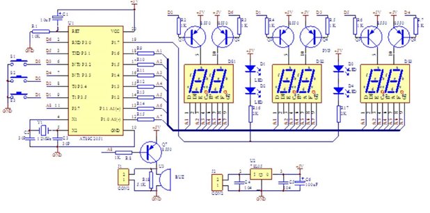
This LED clock kit from EBAY uses 6X S8550 transistor to drive each of the small 0.5 inch LED display


need to use bigger digits 1.8 inch require 7.2 Volt DC to glow.

is it possible to connect 7.2 Volt to these transistors and drive the big LED segments ?

Sure I will keep the 5 volt regulator to supply the PIC chip with fixed 5 volt....

If this is possible, do I need to change the 7 resistors(each is 1 Kohm) going to the a-to-g segments ?


image

  • Sign in to reply
  • Cancel

Top Replies

  • Former Member
    Former Member over 11 years ago +1 suggested
    If you increase the supply for the LEDs to 7.2V (well, greater than that, because you need to account for the voltage drop across the CE junction of the transistor as well as across the current-limiting…
  • mcb1
    mcb1 over 11 years ago in reply to goldenshuttle +1
    The way I see it, you need to add 14 devices. One to each of the pins that connects to the 7 seg LED and the LEDs in between. Yes you may require to change the series resistors to suit the current. I would…
  • Problemchild
    Problemchild over 11 years ago in reply to mcb1 +1
    Yes most use some form of FET or what ever in the bottom of each leg but as you say that would invert the logic required to set the cathodes to a particular logic level.... All personal choice
  • Former Member
    0 Former Member over 11 years ago

    If you increase the supply for the LEDs to 7.2V (well, greater than that, because you need to account for the voltage drop across the CE junction of the transistor as well as across the current-limiting resistor, so let's call it at least 8V), you are increasing the voltage at the emitter of the transistor.  Normally, you would disable the PNP transistor with a HI logic level, which means the base and emitter of the transistor would be at the same potential, not allowing for current to flow from the emitter to the collector or vice-versa.  When you increase the voltage at the emitter, even with a HI (5V) at the base, the PN junction will be forward-biased.  With a HI logic level on all of the LED driving pins, there SHOULD not be enough potential difference to forward bias the segments of the display.  This is definitely not ideal.  Also, there will constantly be a current flowing (or attempting to flow) from the source, through the emitter-base (PN) junction of the transistors, back through the output pins on the micro-controller, even when the pin is at a HI logic level, attempting to turn "off" the transistor.  I don't know what (if any) the potential for damage is here to your micro-controller in this configuration (pin configured as output/low impedence, with HI logic level at the output, with a higher potential attempting to flow back through the pin to the lower potential).

    • Cancel
    • Vote Up +1 Vote Down
    • Sign in to reply
    • Verify Answer
    • Reject Answer
    • Cancel
  • goldenshuttle
    0 goldenshuttle over 11 years ago in reply to Former Member

    Thanks Indeed; true; as the 7.2 flows through the big digits; the voltage would somehow endanger the PIC chip. although by concept, LED will cause a drop in voltage as it passes through...

    so what would be the safe way to replace these small digits with the bigger one's ? can you please give some hints ?

    • Cancel
    • Vote Up 0 Vote Down
    • Sign in to reply
    • Verify Answer
    • Cancel
  • Former Member
    0 Former Member over 11 years ago in reply to goldenshuttle

    One possibility is to use an additional drive transistor, using the 5V logic level from the microcontroller to switch the higher voltage on/off to the base of the transistors which drive the LED's (you'd need one more transistor per digit, plus a couple resistors to limit the base-emitter current and collector current of the new transistors).


    Yes, the digits would cause a voltage drop, and in the "off" state, they shouldn't be flowing any current because there should not be enough voltage difference to forward bias them.  However, the transistors would ALWAYS be forward biased due to the ~ 2 -3 V difference between the higher voltage at the emitters (~8V) and the bases (~5V).  That's an emitter-base current of ~2mA flowing into the microcontroller pins, even when you intend the transistors to be "off", with a 5V logic HI at the base.


    Additionally, you'd need to check the current requirements of the new LED's as you'll likely have to make a change to the current limiting resistors R9 through R15.  If you are going to be sending more current through the transistors, you'll want to check to make sure you won't be exceeding the power dissipation limits.


    I'm sure there's more but that's all I can think of at the moment.

    • Cancel
    • Vote Up 0 Vote Down
    • Sign in to reply
    • Verify Answer
    • Cancel
  • goldenshuttle
    0 goldenshuttle over 11 years ago in reply to Former Member

    I came across this tread; I wonder if it works ?

    I do not want to end up buying one chip for each digit; that is not feasible; even if cheap chips found, the time to solder them is costly

    http://archive.siliconchip.com.au/cms/A_112106/article.html

    • Cancel
    • Vote Up 0 Vote Down
    • Sign in to reply
    • Verify Answer
    • Cancel
  • mcb1
    0 mcb1 over 11 years ago in reply to goldenshuttle

    The way I see it, you need to add 14 devices. One to each of the pins that connects to the 7 seg LED and the LEDs in between.

    Yes you may require to change the series resistors to suit the current.


    I would suggest trying Opto Couplers, since there is no logic conversion, and they will handle the 7.2v without any issues.


    I don't know what (if any) the potential for damage is here to your micro-controller

    The general rule for voltages is NEVER apply a voltage to the IC pin that exceeds the voltage supply to the IC (unless specially designed for it)


    Mark

    • Cancel
    • Vote Up +1 Vote Down
    • Sign in to reply
    • Verify Answer
    • Cancel
  • Problemchild
    0 Problemchild over 11 years ago in reply to mcb1


    Yes most use some form of FET or what ever in the bottom of each leg but as you say that would invert the logic required to set the cathodes to a particular logic level.... All personal choice

    • Cancel
    • Vote Up +1 Vote Down
    • Sign in to reply
    • Verify Answer
    • Cancel
  • shabaz
    0 shabaz over 11 years ago in reply to mcb1

    I also would do the same thing.

    The anode drivers need to be uprated as Mark says, and each cathode needs a driver. Each driver may be  a single device or more even could be a few parts.

    So the circuit ends up quite big unfortunately.

    Sam, if you look at this instructables web page, (about half-way down the page) there is a circuit diagram that shows the type of thing I mean.

    However that circuit would need inverted logic for the anode and cathode ends. So you'd need to change the code to invert the logic, or implement that with additional

    components (e.g. use a few hex inverter ICs).

    If you want to reduce bits, you could use something like ULN2803A which is an octal low side driver, and TLC59213 which is an octal high side driver.

    • Cancel
    • Vote Up +1 Vote Down
    • Sign in to reply
    • Verify Answer
    • Cancel
  • Problemchild
    0 Problemchild over 11 years ago in reply to shabaz

    Shabaz would a change of tack and  the use of one of those 16 channel LED drivers be of interest as each of those LED segments would in fact be only say 3 LEDs and probably in the current limit of the device. In fact if you used 2 of them you could avoid multiplexing altogether and at £1 ish they are probably good value against a large volume of discretes!

    • Cancel
    • Vote Up 0 Vote Down
    • Sign in to reply
    • Verify Answer
    • Cancel
  • shabaz
    0 shabaz over 11 years ago in reply to Problemchild

    Hi John,


    Yes I like those modern LED drivers that you refer to (e.g. TI ones), they are very flexible and have lots of options like PWM and programmable blinking. Very cool.


    Also, the classic MAX7219 is also not a bad alternative, because it still is available in easy-solder through-hole packages.It can drive lots of digits, or individual LEDs. I just noticed there is a circuit in the data sheet showing how to use it to drive large LED displays (larger than the one Sam requires). They use a "hack" where they have a negative supply too. Anyway, that's a digression, since there are other problems anyway such as it would require a complete rewrite of code, since the MAX7219 has a serial interface.

    I've built a couple of clocks with the MAX7219 (one using 7-segment, another using 60 bi-color LEDs) but I don't have the circuit or code any longer due to me losing a computer - I don't make that mistake any more!

    • Cancel
    • Vote Up 0 Vote Down
    • Sign in to reply
    • Verify Answer
    • Cancel
  • Former Member
    0 Former Member over 11 years ago in reply to mcb1

    I didn't even think about opto-couplers.  Replacing the S8550 transistors with opto-couplers could work if you can find ones with enough current handling ability.  I just looked up a quick data sheet, and the collector current on it was only 50mA.  If you could find one that fits the needs, the circuit could even be set up so that no modification would be required to the software (you wouldn't have to invert the logic currently used).

    • Cancel
    • Vote Up 0 Vote Down
    • Sign in to reply
    • Verify Answer
    • Cancel
>
element14 Community

element14 is the first online community specifically for engineers. Connect with your peers and get expert answers to your questions.

  • Members
  • Learn
  • Technologies
  • Challenges & Projects
  • Products
  • Store
  • About Us
  • Feedback & Support
  • FAQs
  • Terms of Use
  • Privacy Policy
  • Legal and Copyright Notices
  • Sitemap
  • Cookies

An Avnet Company © 2025 Premier Farnell Limited. All Rights Reserved.

Premier Farnell Ltd, registered in England and Wales (no 00876412), registered office: Farnell House, Forge Lane, Leeds LS12 2NE.

ICP 备案号 10220084.

Follow element14

  • X
  • Facebook
  • linkedin
  • YouTube