element14 Community
element14 Community
    Register Log In
  • Site
  • Search
  • Log In Register
  • Community Hub
    Community Hub
    • What's New on element14
    • Feedback and Support
    • Benefits of Membership
    • Personal Blogs
    • Members Area
    • Achievement Levels
  • Learn
    Learn
    • Ask an Expert
    • eBooks
    • element14 presents
    • Learning Center
    • Tech Spotlight
    • STEM Academy
    • Webinars, Training and Events
    • Learning Groups
  • Technologies
    Technologies
    • 3D Printing
    • FPGA
    • Industrial Automation
    • Internet of Things
    • Power & Energy
    • Sensors
    • Technology Groups
  • Challenges & Projects
    Challenges & Projects
    • Design Challenges
    • element14 presents Projects
    • Project14
    • Arduino Projects
    • Raspberry Pi Projects
    • Project Groups
  • Products and Partners
    Products and Partners
    • Arduino
    • Avnet & Tria Boards Community
    • Dev Tools
    • Manufacturers
    • Multicomp Pro
    • Product Groups
    • Raspberry Pi
    • RoadTests & Reviews
  • About Us
    About the element14 Community
  • Store
    Store
    • Visit Your Store
    • Choose another store...
      • Europe
      •  Austria (German)
      •  Belgium (Dutch, French)
      •  Bulgaria (Bulgarian)
      •  Czech Republic (Czech)
      •  Denmark (Danish)
      •  Estonia (Estonian)
      •  Finland (Finnish)
      •  France (French)
      •  Germany (German)
      •  Hungary (Hungarian)
      •  Ireland
      •  Israel
      •  Italy (Italian)
      •  Latvia (Latvian)
      •  
      •  Lithuania (Lithuanian)
      •  Netherlands (Dutch)
      •  Norway (Norwegian)
      •  Poland (Polish)
      •  Portugal (Portuguese)
      •  Romania (Romanian)
      •  Russia (Russian)
      •  Slovakia (Slovak)
      •  Slovenia (Slovenian)
      •  Spain (Spanish)
      •  Sweden (Swedish)
      •  Switzerland(German, French)
      •  Turkey (Turkish)
      •  United Kingdom
      • Asia Pacific
      •  Australia
      •  China
      •  Hong Kong
      •  India
      •  Japan
      •  Korea (Korean)
      •  Malaysia
      •  New Zealand
      •  Philippines
      •  Singapore
      •  Taiwan
      •  Thailand (Thai)
      •  Vietnam
      • Americas
      •  Brazil (Portuguese)
      •  Canada
      •  Mexico (Spanish)
      •  United States
      Can't find the country/region you're looking for? Visit our export site or find a local distributor.
  • Translate
  • Profile
  • Settings
Community Hub
Community Hub
Member's Forum How to detect 5V?
  • Blog
  • Forum
  • Documents
  • Quiz
  • Events
  • Leaderboard
  • Polls
  • Files
  • Members
  • Mentions
  • Sub-Groups
  • Tags
  • More
  • Cancel
  • New
Join Community Hub to participate - click to join for free!
Actions
  • Share
  • More
  • Cancel
Forum Thread Details
  • State Verified Answer
  • Replies 14 replies
  • Answers 2 answers
  • Subscribers 632 subscribers
  • Views 3335 views
  • Users 0 members are here
  • zener
  • electronics design
  • led
  • voltage detector
Related

How to detect 5V?

0phoff
0phoff over 10 years ago

Hi everyone,


I'm rather new to electronics but would love to be able to work on projects at home! (now I only do electronics at school)

As a first project, I would love to convert an old Power Supply Unit into a power bench!


I read that PSU have a line called Power Good, which outputs 5V if the PSU is working correctly. I thought it would be cool to connect an LED to this line, so I could see if everything is OK!

For this I first thought of a simple LED+resistor, but then I figured this would make the LED emit light (less bright) even when there is eg. 3V on the line.

So I was thinking of a simple circuit with a zener diode with a breakdown voltage of 5V, but I'm not sure whether this would work as expected...

Since I pay for the components myself, I wanted to be sure this would work, before buying everything!


Can anyone tell me if this idea would work, and if not how to do it otherwise? I've looked on the internet and the main solution I find is with a comparator. I cannot use this because if the PG Line is wrong, I cannot know if the 5V line of the PSU is actually 5V...

What I want is an easy little circuit that has a LED emit light when there is 5V and not emit light when there is no 5V. (doesn't have to be completely exact) As far as I have found, this power good line varies between 0-5V (does not go higher).


Thanksfor your help!


Schematic of my idea:

image

  • Sign in to reply
  • Cancel
Parents
  • shabaz
    0 shabaz over 10 years ago

    Hi,


    Are you sure the power good line isn't a logic level signal (i.e. two states, high and low)? Usually, they output something undefined when the PSU output voltage is very low (e.g. just powering up), then they indicate power bad for the milliseconds that the supply is still coming up, then they indicate power good, then they remain there unless the output voltage is not within some threshold in which case the signal indicates power bad by changing logic level again.

    So, if you have enough power to drive your circuit from the main supply, then you can trust the logic level of the power good signal.

    You could just drive an LED from the main PSU using a resistor and a transistor. Connect the Power Good output via a resistor to the transistor base. Or (even more straightforward, it should only have an extremely dim state during the undefined stage when the voltage is very low), just connect the LED directly to the Power Good line through a resistor.

    • Cancel
    • Vote Up +1 Vote Down
    • Sign in to reply
    • Verify Answer
    • Reject Answer
    • Cancel
  • 0phoff
    0 0phoff over 10 years ago in reply to shabaz

    Ow so you say the PG line would just be 0 or 1 (0 or 5V)... That would idd simplify things!

    I read somewhere that the PG line could be 3V so I guessed it was an analog signal.. Did not find anything else on it so I decided to trust that.. Might do some more research!

    If it's idd just a digital signal that simplifies everything! image

    I'll update the thread when I find out more about this!

    • Cancel
    • Vote Up 0 Vote Down
    • Sign in to reply
    • Verify Answer
    • Cancel
  • shabaz
    0 shabaz over 10 years ago in reply to 0phoff

    It is a guess, it depends on your power supply (google the part number in case you can find user documentation for it).

    It isn't necessarily 5V, but usually is a voltage, e.g. a 12V supply may output 11V if the power is good, and 0V if the power is bad.

    However, you still need to check the documentation, there is no real standard on this. Also, don't assume that the signal means that

    the output is exactly 5V or 12V or whatever your supply is rated at. It could be out by 1 volt or more. It is a crude "go/no-go" indicator.

    • Cancel
    • Vote Up +1 Vote Down
    • Sign in to reply
    • Verify Answer
    • Cancel
  • e14 Contributor
    0 e14 Contributor over 10 years ago in reply to e14 Contributor

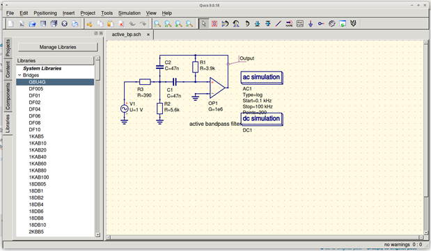
    While TINA-TI seems to work nicely on top of wine for Linux users, I also found a different package, Qucs, which runs natively on Linux (at least, Intel/AMD).  This might eventually be a better fit for the SoCs like RPi since it would probably use less resources.  I am looking through their circuit libraries with the tool on Xubuntu:


    image


    Go here if you are interested (executables and source code): http://qucs.sourceforge.net/

    • Cancel
    • Vote Up 0 Vote Down
    • Sign in to reply
    • Verify Answer
    • Cancel
  • shabaz
    0 shabaz over 10 years ago in reply to jc2048

    Although not needed for this project, there is an awesome silabs part that I found recently, called TS9001 (a couple of variants, open drain or usual totem pole type).

    It is adjustable, so needs additional resistors, but has ultra-low current consumption, the kind of thing that could be used to build a rechargeable or primary cell monitor that could be permanently or semi-permanently! connected, it has about 0.6uA typical, 1.3uA worst-case (25 degrees C) current consumption (and a tiny bit more that would be eaten up with the additional resistor circuit) which was awesome.

    • Cancel
    • Vote Up 0 Vote Down
    • Sign in to reply
    • Verify Answer
    • Cancel
  • jc2048
    0 jc2048 over 10 years ago in reply to Jan Cumps

    That's a neat idea. For a battery monitor, you could alternatively arrange it with a red LED to the supply to indicate that the battery was below the threshold.


    One thing to watch is that the output drive isn't as good as you'd get with a microcontroller I/O pin - 5mA max according to the datasheet.

    • Cancel
    • Vote Up +1 Vote Down
    • Sign in to reply
    • Verify Answer
    • Cancel
  • e14 Contributor
    0 e14 Contributor over 10 years ago in reply to jc2048

    For Linux desktop users, just install the wine package first.  Then, you can install and run TINA-TI as if it were a Windows desktop.  Note that I tested on a Xubuntu desktop system.  If I had a RPi Raspbian desktop, I'd try it there too but I am running OpenELEC.

    • Cancel
    • Vote Up +1 Vote Down
    • Sign in to reply
    • Verify Answer
    • Cancel
  • Jan Cumps
    0 Jan Cumps over 10 years ago in reply to 0phoff

    If the measure needs to be precise, there are dedicated ICs: 'Supply Voltage Supervisors'. They are 3-pin devices that can directly drive an LED if voltage is above a certain threshold.


    For 5 V monitoring, there's the TPS3809I50D (trips at 4.55 V).


    The EEVBlog µCurrent uses a 2.64V one of that family as battery monitor:


    image

    • Cancel
    • Vote Up +4 Vote Down
    • Sign in to reply
    • Verify Answer
    • Reject Answer
    • Cancel
  • 0phoff
    0 0phoff over 10 years ago in reply to jc2048

    Thanks for the explanation! I really appreciate the effort you put into it!

    Putting a 5V zener was a silly mistake idd! And my electronics profesor would kill me if he had known I forgot Kirchoff haha image

    I'll definitely try out the Spice Simulators. (We actually worked with them at university once, so shouldn't be to hard to master... )

    • Cancel
    • Vote Up +2 Vote Down
    • Sign in to reply
    • Verify Answer
    • Cancel
Reply
  • 0phoff
    0 0phoff over 10 years ago in reply to jc2048

    Thanks for the explanation! I really appreciate the effort you put into it!

    Putting a 5V zener was a silly mistake idd! And my electronics profesor would kill me if he had known I forgot Kirchoff haha image

    I'll definitely try out the Spice Simulators. (We actually worked with them at university once, so shouldn't be to hard to master... )

    • Cancel
    • Vote Up +2 Vote Down
    • Sign in to reply
    • Verify Answer
    • Cancel
Children
  • shabaz
    0 shabaz over 10 years ago in reply to jc2048

    Although not needed for this project, there is an awesome silabs part that I found recently, called TS9001 (a couple of variants, open drain or usual totem pole type).

    It is adjustable, so needs additional resistors, but has ultra-low current consumption, the kind of thing that could be used to build a rechargeable or primary cell monitor that could be permanently or semi-permanently! connected, it has about 0.6uA typical, 1.3uA worst-case (25 degrees C) current consumption (and a tiny bit more that would be eaten up with the additional resistor circuit) which was awesome.

    • Cancel
    • Vote Up 0 Vote Down
    • Sign in to reply
    • Verify Answer
    • Cancel
  • jc2048
    0 jc2048 over 10 years ago in reply to Jan Cumps

    That's a neat idea. For a battery monitor, you could alternatively arrange it with a red LED to the supply to indicate that the battery was below the threshold.


    One thing to watch is that the output drive isn't as good as you'd get with a microcontroller I/O pin - 5mA max according to the datasheet.

    • Cancel
    • Vote Up +1 Vote Down
    • Sign in to reply
    • Verify Answer
    • Cancel
  • Jan Cumps
    0 Jan Cumps over 10 years ago in reply to 0phoff

    If the measure needs to be precise, there are dedicated ICs: 'Supply Voltage Supervisors'. They are 3-pin devices that can directly drive an LED if voltage is above a certain threshold.


    For 5 V monitoring, there's the TPS3809I50D (trips at 4.55 V).


    The EEVBlog µCurrent uses a 2.64V one of that family as battery monitor:


    image

    • Cancel
    • Vote Up +4 Vote Down
    • Sign in to reply
    • Verify Answer
    • Reject Answer
    • Cancel
element14 Community

element14 is the first online community specifically for engineers. Connect with your peers and get expert answers to your questions.

  • Members
  • Learn
  • Technologies
  • Challenges & Projects
  • Products
  • Store
  • About Us
  • Feedback & Support
  • FAQs
  • Terms of Use
  • Privacy Policy
  • Legal and Copyright Notices
  • Sitemap
  • Cookies

An Avnet Company © 2026 Premier Farnell Limited. All Rights Reserved.

Premier Farnell Ltd, registered in England and Wales (no 00876412), registered office: Farnell House, Forge Lane, Leeds LS12 2NE.

Follow element14

  • X
  • Facebook
  • linkedin
  • YouTube