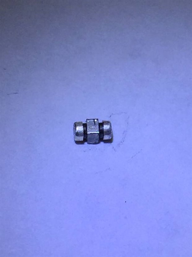
However they usually don't have part value markings so it is not possible to be 100% sure of the replacement.
If you absolutely needed to replace it without more detail then generally you'd use judgement like guesstimate current handling requirement and what frequencies of signal content might be desired to be suppressed.
However, to a first level approximation it is fair to say they will never go wrong (unless it is cracked). So would never need replacing unless you can see visual, physical damage to it.
I'd come across the ones like in the photo below in past work, and so it looked similar but a surface-mount version.
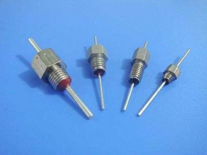
The normal use-case for the ones below is to be used to pass low-frequency signals from inside an enclosure to outside an
enclosure (or vice-versa) or between one separated part of the chassis/enclosure to another part.
Basically they are just a pF- or nF-value capacitor where one terminal is the wire running down the center, and the other terminal is
the metal threaded bit. The wire's inductance, and the capacitor form a filter, to suppress the high frequencies.
So, one of these could be used for supplying the DC power into a circuit inside the chassis/enclosure, and the 0V connection could
just be bolted onto the enclosure which would also be the screen.
I'd never seen the surface-mount versions, but they would have a similar use-case to allow DC supply or low-frequency signals
to pass through to the circuit from one area to another, and suppress high frequencies. Another common way is to use a ferrite bead and a separate capacitor, but that can have layout issues (you don't want the high frequency component coupling itself from one side of the ferrite to the other side) so the integrated approach with the feed-thru method is quite nice.
It's the kind of component that really throws you if you've never seen one before. As you say, it's a form of feedthrough filter.
I've designed them on to boards in the past.
The black area is ferrite. There's a wire through the centre joining the outer terminals. The centre terminal forms a capacitor to the wire and you'd connected it to a quiet earth. The whole thing then forms a 'T' filter - an inductor [very lossy at rf because of the ferrite] in and out and a capacitor in the middle to a quiet ground (not the 0V).
It's for EMC filtering of a supply line to a board.
That one can manage up to 5 or 6A, which was pretty unique when Murata introduced it - maybe people make copies now, though I don't ever see them on boards. They're expensive compared to beads; we [the company I worked for at the time] moved away from using them because we got good enough results for what we needed with a pair of SMD beads and small SMD capacitors.
In case it's not obvious, the structure is symmetrical because (for EMC purposes) you're trying to stop rf energy generated by your circuit getting off the board and then radiating from the wiring, as well as stopping rf energy coming in from the wiring and affecting your circuit (in a lot of situations, the wiring in a piece of equipment makes for a much better aerial [antenna] than the board traces and components).
If you have a single supply coming on to a board, you'd use one for the positive and one for the negative - it's an rf filter and it's no good filtering the positive only as the rf noise will just skip to the 0V [through one of the small capacitors that you helpfully provide where the + and - come on to the board] and exit that way.
Good comment about PCB layout being vital: no point in going to all the trouble of filtering if the noise can just casually skip round it.