element14 Community
element14 Community
    Register Log In
  • Site
  • Search
  • Log In Register
  • Community Hub
    Community Hub
    • What's New on element14
    • Feedback and Support
    • Benefits of Membership
    • Personal Blogs
    • Members Area
    • Achievement Levels
  • Learn
    Learn
    • Ask an Expert
    • eBooks
    • element14 presents
    • Learning Center
    • Tech Spotlight
    • STEM Academy
    • Webinars, Training and Events
    • Learning Groups
  • Technologies
    Technologies
    • 3D Printing
    • FPGA
    • Industrial Automation
    • Internet of Things
    • Power & Energy
    • Sensors
    • Technology Groups
  • Challenges & Projects
    Challenges & Projects
    • Design Challenges
    • element14 presents Projects
    • Project14
    • Arduino Projects
    • Raspberry Pi Projects
    • Project Groups
  • Products
    Products
    • Arduino
    • Avnet Boards Community
    • Dev Tools
    • Manufacturers
    • Multicomp Pro
    • Product Groups
    • Raspberry Pi
    • RoadTests & Reviews
  • Store
    Store
    • Visit Your Store
    • Choose another store...
      • Europe
      •  Austria (German)
      •  Belgium (Dutch, French)
      •  Bulgaria (Bulgarian)
      •  Czech Republic (Czech)
      •  Denmark (Danish)
      •  Estonia (Estonian)
      •  Finland (Finnish)
      •  France (French)
      •  Germany (German)
      •  Hungary (Hungarian)
      •  Ireland
      •  Israel
      •  Italy (Italian)
      •  Latvia (Latvian)
      •  
      •  Lithuania (Lithuanian)
      •  Netherlands (Dutch)
      •  Norway (Norwegian)
      •  Poland (Polish)
      •  Portugal (Portuguese)
      •  Romania (Romanian)
      •  Russia (Russian)
      •  Slovakia (Slovak)
      •  Slovenia (Slovenian)
      •  Spain (Spanish)
      •  Sweden (Swedish)
      •  Switzerland(German, French)
      •  Turkey (Turkish)
      •  United Kingdom
      • Asia Pacific
      •  Australia
      •  China
      •  Hong Kong
      •  India
      •  Korea (Korean)
      •  Malaysia
      •  New Zealand
      •  Philippines
      •  Singapore
      •  Taiwan
      •  Thailand (Thai)
      • Americas
      •  Brazil (Portuguese)
      •  Canada
      •  Mexico (Spanish)
      •  United States
      Can't find the country/region you're looking for? Visit our export site or find a local distributor.
  • Translate
  • Profile
  • Settings
Community Hub
Community Hub
Member's Forum Please Help!
  • Blog
  • Forum
  • Documents
  • Quiz
  • Events
  • Leaderboard
  • Polls
  • Files
  • Members
  • Mentions
  • Sub-Groups
  • Tags
  • More
  • Cancel
  • New
Join Community Hub to participate - click to join for free!
Actions
  • Share
  • More
  • Cancel
Forum Thread Details
  • State Not Answered
  • Replies 6 replies
  • Subscribers 507 subscribers
  • Views 502 views
  • Users 0 members are here
Related

Please Help!

sailmike1
sailmike1 over 12 years ago

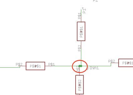
I'm new fairly new to Eagle software. I've already figured out how to make custom parts and add them to the schematic. I'm currently trying to route all the wires, but only some of the wires are getting connected. I have no idea why. Here's a screenshot of part of my circuit showing one of the bandpass amplifiers with the net wires done and named.

image

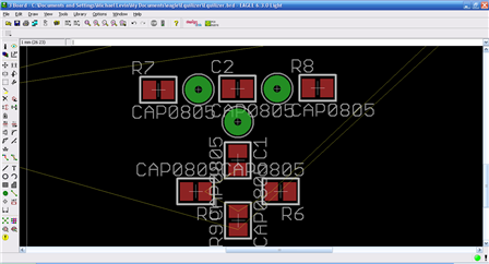
Here's a screenshot of the board showing the same bandpass amplifier with only some of the wires connected with the yellow airwires I think they are called.

image


I appreciate any help you guys can give me. I'm so frustrated now. I've tried wiring in different ways. I've redone the whole thing several times to no avail.


Thank you,

Mike

  • Sign in to reply
  • Cancel
  • shabaz
    0 shabaz over 12 years ago

    Hi Michael,


    It looks like on the schematic, the pins are actually not connected to the green wires, they are just "close" to the green wires.

    You can test by trying to move a component. If the component moves but the wires do not move along with the component, then they are not connected.

    The giveaway would be this:

    image

    It should not be possible to have blobs so close to each other, unless you've modified the grid setting:

    image

    Basically, on the schematic view, you should never change the grid setting from the default (0.1inch). All components are/should be designed such that they can be wired up using the default grid setting.

    You should only need to modify the grid setting on the board view, or when creating parts.

    • Cancel
    • Vote Up 0 Vote Down
    • Sign in to reply
    • Verify Answer
    • Cancel
  • sailmike1
    0 sailmike1 over 12 years ago in reply to shabaz

    I want the default in metric not American standard. How do I change the default to metric? Also, if I create the parts in metric, they won't get connected on the schematic when American standard is used.


    Thank you,

    Mike

    • Cancel
    • Vote Up 0 Vote Down
    • Sign in to reply
    • Verify Answer
    • Cancel
  • shabaz
    0 shabaz over 12 years ago in reply to sailmike1

    Hi Michael,


    A component (device) comprises of the symbol (i.e. logical representation) and the package (physical representation).

    All EAGLE components use a symbol in imperial measurement system. The package can be metric or imperial.


    For the schematic (which is a logical view, not physical) it doesn't really matter what the unit is, except that the component symbols must also be created with the same unit.

    As mentioned, all the existing symbols are based on a 0.1inch grid, so it's unfeasible to change this unless you're prepared to manually create every schematic symbol you'll ever need.


    On your physical board view, you can change to metric if you wish, using the grid icon.


    Your final PCB certainly can use some parts that are dimensioned metric and others that may be imperial. This is normal practise; some component manufacturers dimension in metric (e.g. 1mm), others dimension in imperial (e.g. 0.05inch) and metric (e.g. 1.27mm).

    • Cancel
    • Vote Up 0 Vote Down
    • Sign in to reply
    • Verify Answer
    • Cancel
  • sailmike1
    0 sailmike1 over 12 years ago in reply to shabaz

    Well, my thinking is that I've noticed that the data sheet for nearly all components are listed in metric so it makes sense to me to use metric to make the parts I need rather than always converting everytime I need to create a part. You said the component symbol needs to be created in the same measurement as the schematic not the package?


    By the way, your tip on moving the part to see if the wire is connected worked. I found that moving the part and making sure that the pin was on top of the wire before clicking again connects them.


    Thanks for your quick reply,

    Mike

    • Cancel
    • Vote Up 0 Vote Down
    • Sign in to reply
    • Verify Answer
    • Cancel
  • shabaz
    0 shabaz over 12 years ago in reply to sailmike1

    A datasheet only specifies dimensions for the physical part, e.g. this capacitor:

    image

    However, the logical symbol (schematic symbol) for a capacitor is dimensionless, e.g.:

    image

    There is no datasheet that defines dimensions for a schematic symbol; it is like trying to put a linear dimension on a music note on a music sheet (the music sounds the same regardless of the size of the music sheet).


    It just happens that for drawing purposes, the schematic symbol in EAGLE is always specified in inches grid; it's not 'right' or 'wrong', it's just that a unit is required due to the implementation. You're strongly advised (but not forced) to use inches, since then you can make use of the existing schematic symbols in EAGLE, rather than reinvent the wheel. Otherwise, if you really want metric on a schematic (why?), you could try to set the grid to 2.54mm (I personally wouldn't try this, because of rounding errors which may cause big problems on a spread-out schematic layout).


    For physical symbols (package), it's a different matter: you're free to (and should) define the physical symbol in metric or imperial, whichever suits the component/datasheet.

    • Cancel
    • Vote Up 0 Vote Down
    • Sign in to reply
    • Verify Answer
    • Cancel
  • sailmike1
    0 sailmike1 over 12 years ago in reply to shabaz

    Ah, I gotcha. I've got the board routed now.


    Thanks for your help,

    Mike

    • Cancel
    • Vote Up 0 Vote Down
    • Sign in to reply
    • Verify Answer
    • Cancel
element14 Community

element14 is the first online community specifically for engineers. Connect with your peers and get expert answers to your questions.

  • Members
  • Learn
  • Technologies
  • Challenges & Projects
  • Products
  • Store
  • About Us
  • Feedback & Support
  • FAQs
  • Terms of Use
  • Privacy Policy
  • Legal and Copyright Notices
  • Sitemap
  • Cookies

An Avnet Company © 2025 Premier Farnell Limited. All Rights Reserved.

Premier Farnell Ltd, registered in England and Wales (no 00876412), registered office: Farnell House, Forge Lane, Leeds LS12 2NE.

ICP 备案号 10220084.

Follow element14

  • X
  • Facebook
  • linkedin
  • YouTube