element14 Community
element14 Community
    Register Log In
  • Site
  • Search
  • Log In Register
  • Community Hub
    Community Hub
    • What's New on element14
    • Feedback and Support
    • Benefits of Membership
    • Personal Blogs
    • Members Area
    • Achievement Levels
  • Learn
    Learn
    • Ask an Expert
    • eBooks
    • element14 presents
    • Learning Center
    • Tech Spotlight
    • STEM Academy
    • Webinars, Training and Events
    • Learning Groups
  • Technologies
    Technologies
    • 3D Printing
    • FPGA
    • Industrial Automation
    • Internet of Things
    • Power & Energy
    • Sensors
    • Technology Groups
  • Challenges & Projects
    Challenges & Projects
    • Design Challenges
    • element14 presents Projects
    • Project14
    • Arduino Projects
    • Raspberry Pi Projects
    • Project Groups
  • Products
    Products
    • Arduino
    • Avnet Boards Community
    • Dev Tools
    • Manufacturers
    • Multicomp Pro
    • Product Groups
    • Raspberry Pi
    • RoadTests & Reviews
  • About Us
  • Store
    Store
    • Visit Your Store
    • Choose another store...
      • Europe
      •  Austria (German)
      •  Belgium (Dutch, French)
      •  Bulgaria (Bulgarian)
      •  Czech Republic (Czech)
      •  Denmark (Danish)
      •  Estonia (Estonian)
      •  Finland (Finnish)
      •  France (French)
      •  Germany (German)
      •  Hungary (Hungarian)
      •  Ireland
      •  Israel
      •  Italy (Italian)
      •  Latvia (Latvian)
      •  
      •  Lithuania (Lithuanian)
      •  Netherlands (Dutch)
      •  Norway (Norwegian)
      •  Poland (Polish)
      •  Portugal (Portuguese)
      •  Romania (Romanian)
      •  Russia (Russian)
      •  Slovakia (Slovak)
      •  Slovenia (Slovenian)
      •  Spain (Spanish)
      •  Sweden (Swedish)
      •  Switzerland(German, French)
      •  Turkey (Turkish)
      •  United Kingdom
      • Asia Pacific
      •  Australia
      •  China
      •  Hong Kong
      •  India
      •  Korea (Korean)
      •  Malaysia
      •  New Zealand
      •  Philippines
      •  Singapore
      •  Taiwan
      •  Thailand (Thai)
      • Americas
      •  Brazil (Portuguese)
      •  Canada
      •  Mexico (Spanish)
      •  United States
      Can't find the country/region you're looking for? Visit our export site or find a local distributor.
  • Translate
  • Profile
  • Settings
Community Hub
Community Hub
Member's Forum Wat is the oldest chip in your parts bin?
  • Blog
  • Forum
  • Documents
  • Quiz
  • Events
  • Leaderboard
  • Polls
  • Files
  • Members
  • Mentions
  • Sub-Groups
  • Tags
  • More
  • Cancel
  • New
Join Community Hub to participate - click to join for free!
Actions
  • Share
  • More
  • Cancel
Forum Thread Details
  • Replies 45 replies
  • Subscribers 549 subscribers
  • Views 4533 views
  • Users 0 members are here
  • MC6800
  • 2708
  • z80
  • old ICs
  • old chips
Related

Wat is the oldest chip in your parts bin?

dougw
dougw over 2 years ago

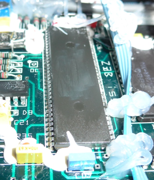
I came across some old and famous chips in one of my parts cabinets. Does anybody else keep old chips? and why?

Note that these were pretty expensive when they were purchased, especially the gold plated ceramic chips.

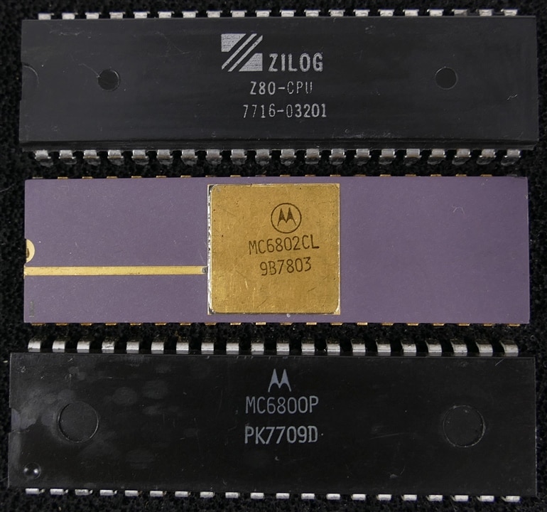
I expect most of these are part numbers that everyone has heard of.

Have you designed with any of these famous chips?

Brownie points if you can figure out the date codes.

image

image

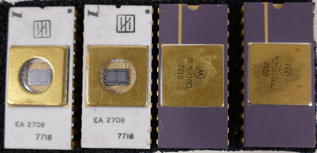
What chips are buried in your archives?

  • Sign in to reply
  • Cancel

Top Replies

  • ralphjy
    ralphjy over 2 years ago +8
    I used to design with a lot of Signetics parts in the 70's. I've got one of the early 555 parts. Shown here with a 566 VCO and 5556 opamp. I probably have some of the 56x series PLLs around somewhere…
  • baldengineer
    baldengineer over 2 years ago +6
    I was excited because I thought I'd have a real contender. But, today is the first time I ever looked the date code, which is on the bottom. It's from a run in 1980. So I probably have MOS 6502 chips…
  • Jan Cumps
    Jan Cumps over 2 years ago +6
    oldest I had: image source . I don't have that kit anymore.
Parents
  • beacon_dave
    beacon_dave over 2 years ago
    dougw said:
    Have you designed with any of these famous chips?

    Not sure if this counts but I've been getting pretty intimate with Hitachi's HD6303 in recent years which shares some history with the original 6800 series.

    A now retired colleague of mine accidentally bought one as part of a rather unique classic car which uses it as part of its engine control unit. 

    It all started with a photo like this and of course no documentation...

    image

    The manufacture appeared to enjoy obfuscating IC numbers on the early units either by erasing or covering with hot glue...  

    • Cancel
    • Vote Up +3 Vote Down
    • Sign in to reply
    • Cancel
  • dang74
    dang74 over 2 years ago in reply to beacon_dave

    Nice.  Sounds like the beginnings of a journey.  I have to admire the patience of tackling anything where the documentation is lacking.

    • Cancel
    • Vote Up +2 Vote Down
    • Sign in to reply
    • Cancel
  • beacon_dave
    beacon_dave over 2 years ago in reply to dang74

    What made it more difficult was that there was no second chance here and time was not on our side. There was engine mapping and configuration data stored inside a 'black box' that had to be extracted before it became corrupted due to the length of time. The system was last programmed around 35 years ago. The car was a bespoke demonstrator and unique in many ways so not as if you can just copy it from another vehicle if it doesn't end well.

    Needless to say, the original diagnostics equipment used to connect to, configure, and update the mappings was missing, along with its software.

    All there was to go on were two unmarked Fischer automotive connectors on the box, one 5-pin, one 3-pin and that somehow that was the way into the system. Initial probing with a scope revealed no clock or data signal, as it turned out that the diagnostics side initiated the (undocumented) comms.

    Also I had no physical access to the device at the start as this 'project' was initiated during the first COVID lockdown period.

    • Cancel
    • Vote Up +3 Vote Down
    • Sign in to reply
    • Cancel
  • dang74
    dang74 over 2 years ago in reply to beacon_dave

    Does the code that the HD6303 runs reside in an external ROM?  If so, maybe it's possible to read back the contents.  Then of course you would have to find some method to do a disassembly of the raw binary.  It would be too much work for me. LOL.

    • Cancel
    • Vote Up +3 Vote Down
    • Sign in to reply
    • Cancel
  • beacon_dave
    beacon_dave over 2 years ago in reply to dang74

    The code on the HD6303 is held in an external EEPROM, so that gets corrupted along with the rest of the EEPROM data at some point in the not too distant future.

    I've already managed to access the contents of the EEPROM and extracted the raw HD6303 binary data from it. I've also already written a HD6303 disassembler and now have a 6303 assembly language listing to work with.

    Although I generally understand the individual 6303 instructions, what I'm struggling with is following the overall program flow. Every few instructions is a branch or jump and I find it hard keep track of what is actually going on. I've worked out some stuff though and commented about a quarter of it. Not sure if I should be looking at writing a basic debugger / interpreter so as I can step through the instructions one at a time and outputting the  register contents. 

    I've worked out quite a bit of the overall address space - in addition to the processor and EEPROM there are five external analogue data acquisition units each of which contain three timers. Four of those ADUs are used to fire the 12 fuel injector pulses. The address decoding needs some more investigation work as I appear to see ghost data as if multiple address locations are pointing at the same registers due to the way the decoding is being done.

    I've worked out most of the comms protocol now, however there is some 'engine math' that I'm not sure about in order to be able to convert from the parameter data to human data. I've got a lot of it logged as look-up tables and plotted the curves, but would be nice to understand the math that was actually used.

    • Cancel
    • Vote Up +3 Vote Down
    • Sign in to reply
    • Cancel
Reply
  • beacon_dave
    beacon_dave over 2 years ago in reply to dang74

    The code on the HD6303 is held in an external EEPROM, so that gets corrupted along with the rest of the EEPROM data at some point in the not too distant future.

    I've already managed to access the contents of the EEPROM and extracted the raw HD6303 binary data from it. I've also already written a HD6303 disassembler and now have a 6303 assembly language listing to work with.

    Although I generally understand the individual 6303 instructions, what I'm struggling with is following the overall program flow. Every few instructions is a branch or jump and I find it hard keep track of what is actually going on. I've worked out some stuff though and commented about a quarter of it. Not sure if I should be looking at writing a basic debugger / interpreter so as I can step through the instructions one at a time and outputting the  register contents. 

    I've worked out quite a bit of the overall address space - in addition to the processor and EEPROM there are five external analogue data acquisition units each of which contain three timers. Four of those ADUs are used to fire the 12 fuel injector pulses. The address decoding needs some more investigation work as I appear to see ghost data as if multiple address locations are pointing at the same registers due to the way the decoding is being done.

    I've worked out most of the comms protocol now, however there is some 'engine math' that I'm not sure about in order to be able to convert from the parameter data to human data. I've got a lot of it logged as look-up tables and plotted the curves, but would be nice to understand the math that was actually used.

    • Cancel
    • Vote Up +3 Vote Down
    • Sign in to reply
    • Cancel
Children
  • anniel747
    anniel747 over 2 years ago in reply to beacon_dave

    Bit rot often kills undocumented electronics. Sad.

    • Cancel
    • Vote Up +2 Vote Down
    • Sign in to reply
    • Cancel
  • dang74
    dang74 over 2 years ago in reply to beacon_dave

    That is an amazing amount of effort especially writing your own dissambler.  The programmers of yesterday did seem to like jumping in and out of subroutines.  I formed that opinion, anyway, after seeing the dissasmbly of some Intellivision games.  And truth be told I couldn't extract enough meaning from the generated code to make any sense of it.  Best of luck if you ever resume this project again.

    • Cancel
    • Vote Up +3 Vote Down
    • Sign in to reply
    • Cancel
  • beacon_dave
    beacon_dave over 2 years ago in reply to dang74

    Actually, I found that was one of the easier parts as Hitachi had a datasheet on the HD6303 so I had the opcode map and the number of operands each opcode expected. I knew where the processor looked for the interrupt vector table in memory so the value stored there at told me the address where the executable code started. From there it is just a case of looking up the opcode and then finding how many operands it expects and away you go. It was a bit tedious as the data sheet was scanned so no quick cut and paste into the program. Add in a few extra routines to calculate addressing offsets to make it more readable. In-line data can be an issue. Also keeping an eye on the interrupt vector table can identify start addresses of other code blocks.  

    If you want effort, then that was months of looking at data captures from a scope trying to figure out patterns in the data. It turned out that the comms was asymmetrically encoded so the few ASCII characters in the config section were initially obfuscated. Then finally once I had identified the encoding method there was a 'Twin Peaks moment' 

    https://www.youtube.com/watch?v=mbi7rq-TSk8&t=78s

    as the hex sequence for the Program ID and data ID strings finally matched one of the data captures and confirmed I was really on the right track.

    If the code was originally generated from an optimising compiler, then it often can often be hard to follow as the optimisation can save program cycles by doing certain procedures in rather non-intuitive ways. Also by having lots of near jumps you can reduce the overall code size to fit in the limited memory by reusing code blocks, however once again it makes it a lot harder to follow.

    It would make life easier I think if I had a way of turning the listing into a graphical diagram with the blocks of code linked by the jumps such that you could slide things around so that the related sections were next to each other. Also a way of labelling and commenting what you had identified so far. I think that's what the call 'data graph' structures in programming lingo ?  I once saw this done manually with string and post-it notes !

    If I was a bit further along the line, then I might have given the LabVIEW challenge a go using it to connect to the ECU (or rather the ECU protocol simulator that I have also written as part of this project). However  I'm not sure what is involved in getting LabVIEW to talk to the ECU protocol and parse the data.

    • Cancel
    • Vote Up +3 Vote Down
    • Sign in to reply
    • Cancel
  • anniel747
    anniel747 over 2 years ago in reply to beacon_dave

    Something like Ghidra would have been useful.

    • Cancel
    • Vote Up +1 Vote Down
    • Sign in to reply
    • Cancel
  • dang74
    dang74 over 2 years ago in reply to beacon_dave
    beacon_dave said:
    Also by having lots of near jumps you can reduce the overall code size to fit in the limited memory by reusing code blocks, however once again it makes it a lot harder to follow.

    This has been my observation as well.  Thirty to forty years ago memory size was limited so reuse was the key.  Now us poor suckers that are trying to reverse engineer code from that era are paying the price.

    • Cancel
    • Vote Up +2 Vote Down
    • Sign in to reply
    • Cancel
  • beacon_dave
    beacon_dave over 2 years ago in reply to anniel747

    If you can import the data. I don't think it supports HD6303 assembly ?

    I've had a bit of a look at Ghidra and IDA Pro in the past but I've not found much training material surrounding the older platforms.

    • Cancel
    • Vote Up +1 Vote Down
    • Sign in to reply
    • Cancel
  • anniel747
    anniel747 over 2 years ago in reply to beacon_dave

    You need to add the instruction set with SLEIGH.

    • Cancel
    • Vote Up +1 Vote Down
    • Sign in to reply
    • Cancel
  • beacon_dave
    beacon_dave over 2 years ago in reply to anniel747

    Now that sounds very interesting.

    If there is an equivalent SLEIGH model already for the MC6800, then it may be fairly straightforward to add the additional features and to tweak the quirks.

    Down another 'rabbit hole' we go...

    • Cancel
    • Vote Up +1 Vote Down
    • Sign in to reply
    • Cancel
element14 Community

element14 is the first online community specifically for engineers. Connect with your peers and get expert answers to your questions.

  • Members
  • Learn
  • Technologies
  • Challenges & Projects
  • Products
  • Store
  • About Us
  • Feedback & Support
  • FAQs
  • Terms of Use
  • Privacy Policy
  • Legal and Copyright Notices
  • Sitemap
  • Cookies

An Avnet Company © 2025 Premier Farnell Limited. All Rights Reserved.

Premier Farnell Ltd, registered in England and Wales (no 00876412), registered office: Farnell House, Forge Lane, Leeds LS12 2NE.

ICP 备案号 10220084.

Follow element14

  • X
  • Facebook
  • linkedin
  • YouTube