element14 Community
element14 Community
    Register Log In
  • Site
  • Search
  • Log In Register
  • Community Hub
    Community Hub
    • What's New on element14
    • Feedback and Support
    • Benefits of Membership
    • Personal Blogs
    • Members Area
    • Achievement Levels
  • Learn
    Learn
    • Ask an Expert
    • eBooks
    • element14 presents
    • Learning Center
    • Tech Spotlight
    • STEM Academy
    • Webinars, Training and Events
    • Learning Groups
  • Technologies
    Technologies
    • 3D Printing
    • FPGA
    • Industrial Automation
    • Internet of Things
    • Power & Energy
    • Sensors
    • Technology Groups
  • Challenges & Projects
    Challenges & Projects
    • Design Challenges
    • element14 presents Projects
    • Project14
    • Arduino Projects
    • Raspberry Pi Projects
    • Project Groups
  • Products
    Products
    • Arduino
    • Avnet & Tria Boards Community
    • Dev Tools
    • Manufacturers
    • Multicomp Pro
    • Product Groups
    • Raspberry Pi
    • RoadTests & Reviews
  • About Us
    About the element14 Community
  • Store
    Store
    • Visit Your Store
    • Choose another store...
      • Europe
      •  Austria (German)
      •  Belgium (Dutch, French)
      •  Bulgaria (Bulgarian)
      •  Czech Republic (Czech)
      •  Denmark (Danish)
      •  Estonia (Estonian)
      •  Finland (Finnish)
      •  France (French)
      •  Germany (German)
      •  Hungary (Hungarian)
      •  Ireland
      •  Israel
      •  Italy (Italian)
      •  Latvia (Latvian)
      •  
      •  Lithuania (Lithuanian)
      •  Netherlands (Dutch)
      •  Norway (Norwegian)
      •  Poland (Polish)
      •  Portugal (Portuguese)
      •  Romania (Romanian)
      •  Russia (Russian)
      •  Slovakia (Slovak)
      •  Slovenia (Slovenian)
      •  Spain (Spanish)
      •  Sweden (Swedish)
      •  Switzerland(German, French)
      •  Turkey (Turkish)
      •  United Kingdom
      • Asia Pacific
      •  Australia
      •  China
      •  Hong Kong
      •  India
      •  Japan
      •  Korea (Korean)
      •  Malaysia
      •  New Zealand
      •  Philippines
      •  Singapore
      •  Taiwan
      •  Thailand (Thai)
      •  Vietnam
      • Americas
      •  Brazil (Portuguese)
      •  Canada
      •  Mexico (Spanish)
      •  United States
      Can't find the country/region you're looking for? Visit our export site or find a local distributor.
  • Translate
  • Profile
  • Settings
Community Hub
Community Hub
Member's Forum SuperCap Sunday - Two Capacitor Paradox
  • Blog
  • Forum
  • Documents
  • Quiz
  • Events
  • Leaderboard
  • Polls
  • Files
  • Members
  • Mentions
  • Sub-Groups
  • Tags
  • More
  • Cancel
  • New
Join Community Hub to participate - click to join for free!
Actions
  • Share
  • More
  • Cancel
Forum Thread Details
  • Replies 25 replies
  • Subscribers 607 subscribers
  • Views 3462 views
  • Users 0 members are here
Related

SuperCap Sunday - Two Capacitor Paradox

scottiebabe
scottiebabe over 2 years ago

The following phenomenon is even more mysterious than KFC’s secret recipe or where do socks go.

When you connect a charged capacitor in parallel to a discharged capacitor of the same capacitance half the stored energy disappears!

image
Source: Wiki

See a full detailed analysis at: en.wikipedia.org/.../Two_capacitor_paradox

I will attempt to demonstrate this behavior using supercaps and some primitive instrumentation.

  • 2x EDLC SuperCapacitor 2.5F 5.5V
  • Adjustable power supply
  • USB power meter
  • 50 Ohm resistor

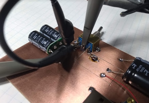
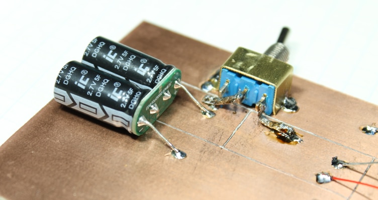
Here is the test apparatus:

image

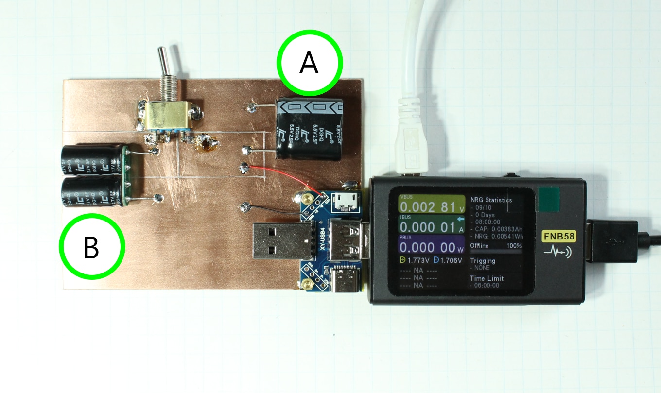
The 2 DUT capacitors share a common ground and a toggle switch allows for the positive terminals be isolated or shorted together.

I first measured the charge and energy stored in DUT-A by charging the capacitor to 5 V and then recording the effective output charge and energy when a 50 ohm resistor is used as a test load. I repeated the test a few time to get a vague ideal how repeatable the test setup was. Here is a screenshot of the recorded test runs on my USB power meter.

image

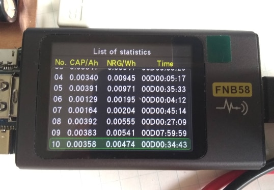
After a few minutes of data entry into excel here are all the test run results.

image

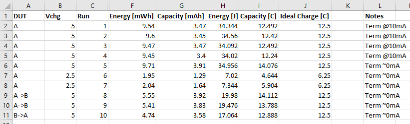
How long the capacitor was charged likely and allow to soak at its test voltage likely lead to some variability in the test. At first I had my power meter stop recorded when the discharge current declined below 10 mA. Later on, I manually terminated the test when the DUT registered less than 1 mA of discharge current into the test load.

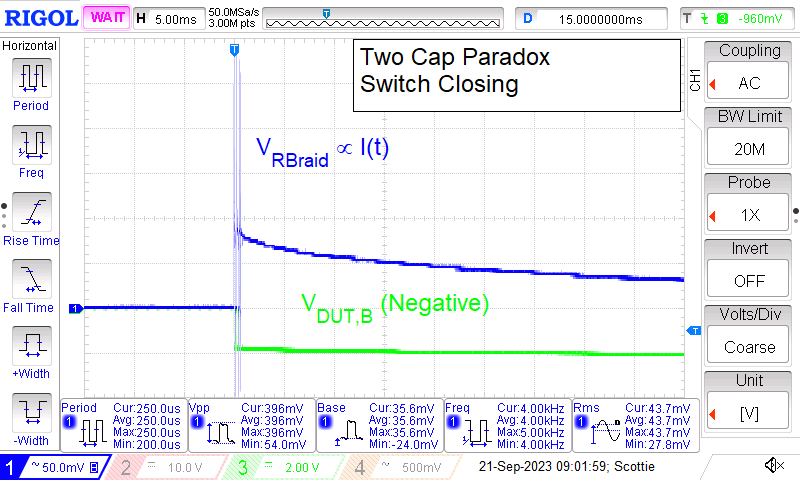
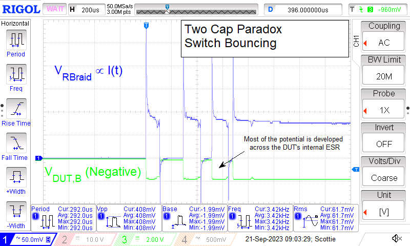
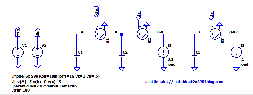
Finally the big moment! I charged DUT-A to 5 V and discharged DUT-B to 0 V. Then looking the other direction flipped the toggle switch which placed the 2 DUT capacitors in parallel with a low ohm connection.

No noise, no smoke, no excitement, no welded switch contacts… Somewhat anti-climatic.

I measured the voltage across the now parallel capacitors at 2.881 V. Assuming both capacitors were equal and ideal, the voltage should have declined to 2.5 V (half of the 5 V test stimulus). Capacitor DUT-B likely has a lower effective capacitance compared to that of DUT-A. Testing a second time resulted in final voltage of 2.848 V.

Was the charge of DUT-A conserved? Yes, the measured charge was within the margin of uncertainty of the test setup.

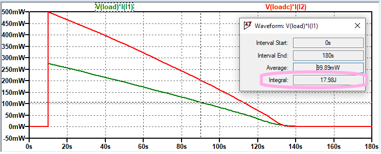
Where’s the energy? The recorded energy of the parallel DUT capacitors is 56% that of the energy that was originally stored in DUT-A prior to being connected to discharged DUT-B.

Where did the energy go!?

Repeating the experiment in the opposite direction, charging DUT-B and connected discharged DUT-A resulted in a final voltage of 2.658 V.

There is lots that could be improved and the voltage coefficient of capacitance of my EDLCs also played role in leaving a little extra energy in the system.

But, I would say its an easy DIY experiment if you want to have some SuperFun.

  • Sign in to reply
  • Cancel
  • colporteur
    colporteur over 2 years ago in reply to scottiebabe

    Thank you for sharing your insight. It was the answer I was looking for.

    You use your experience to gain knowledge to make changes that improve the experience. The simple idea of reading the component values is an example.

    I find your posts and  dougw are similar. I am both fascinating and envious of the process you follow to arrive at the solution. "Now why didn't I think of that....or I would never have thought of that..." are common utterances after following one of your projects.

    Your contributions are a great asset to the community..

    • Cancel
    • Vote Up +2 Vote Down
    • Sign in to reply
    • Cancel
  • scottiebabe
    scottiebabe over 2 years ago

    Scope Shots

    Probe locations:

    image

    image

    image

    • Cancel
    • Vote Up +5 Vote Down
    • Sign in to reply
    • Cancel
  • scottiebabe
    scottiebabe over 2 years ago in reply to colporteur

    lol thank you for the kind words. I wish I had an elaborate answer but the three main reasons were:

    Show: Looks cool and it easy to read the component markings when they are on their side for a photo op

    Impedance: Rule of thumb for the resistance of 1 oz copper is 0.5 mOhm/sq ( so a few big squares between circuit points has a much lower resistance than a long chain of squares you would find in a skinny trace and lower inductance too). Here I am sourcing 1 A between the two negative capacitor leads and measuring the voltage drop

    image

    That works out to be 4.84 mOhms. If I probe the voltage drop on the copper near the solder joint the resistance between mounting locations measures 2.7 mOhms. Could be better but its an order of magnitude or two lower than the ESR internal to the capacitor so its good enough for a fun demonstration piece.

    Mechanical Strength: The pads on cheap perf boards are pretty hopeless at staying attached to the board if you solder the component surface mount versus through hole. Its easier to swap or recover the DUTs this way versus had they been soldered through hole.

    • Cancel
    • Vote Up +3 Vote Down
    • Sign in to reply
    • Cancel
  • colporteur
    colporteur over 2 years ago

    Your approach to scoring a copper clad PCB to make a small circuit is novel. I like! Why this over a perf board? Please develop some elaborate answer and not, "Oh had a strip of board kicking around I wasn't using.:)

    • Cancel
    • Vote Up +1 Vote Down
    • Sign in to reply
    • Cancel
  • dang74
    dang74 over 2 years ago in reply to scottiebabe

    Like the mental image of 'counting electrons on a factory floor.'

    • Cancel
    • Vote Up +1 Vote Down
    • Sign in to reply
    • Cancel
  • anniel747
    anniel747 over 2 years ago in reply to scottiebabe

    That's wicked.

    • Cancel
    • Vote Up +3 Vote Down
    • Sign in to reply
    • Cancel
  • scottiebabe
    scottiebabe over 2 years ago

    I even got to use leftover solder braid lol

    image

    • Cancel
    • Vote Up +4 Vote Down
    • Sign in to reply
    • Cancel
  • scottiebabe
    scottiebabe over 2 years ago

    If you want to try the experiment in spice here is one approach:

    image

    Then compare the energy dissipated in active loads I1 and I2

    image

    E_I1 = 17.98J

    E_I2 = 33.315J

    E_I1/E_I2 = 53.97% ( Note I used capacitors with a voltage coefficient in this example)

    If you use ideal capacitors you will get the 50% figure. Don't plot the energy dissipated in the resistive elements, that's cheating!

    • Cancel
    • Vote Up +3 Vote Down
    • Sign in to reply
    • Cancel
  • md_steve
    md_steve over 2 years ago in reply to scottiebabe

    And here I was mystified by my dog's walking schedule.. 

    • Cancel
    • Vote Up +4 Vote Down
    • Sign in to reply
    • Cancel
  • scottiebabe
    scottiebabe over 2 years ago in reply to anniel747

    lol I corrected my mistake in L6, the capacity in coulombs was determined once the DUT was essentially completely discharged as opposed to 10 mA.

    The charge of DUT-A was conversed.  Of course there are lots of other ways to measure the energy and charge, with say the math functions on a DSO different problems there with input offset and accuracy.

    I have seen some integrate and dump coulomb counter ic's cant remember the pn, but I doubt they would tolerate a 100 mA input current.

    • Cancel
    • Vote Up +1 Vote Down
    • Sign in to reply
    • Cancel
>
element14 Community

element14 is the first online community specifically for engineers. Connect with your peers and get expert answers to your questions.

  • Members
  • Learn
  • Technologies
  • Challenges & Projects
  • Products
  • Store
  • About Us
  • Feedback & Support
  • FAQs
  • Terms of Use
  • Privacy Policy
  • Legal and Copyright Notices
  • Sitemap
  • Cookies

An Avnet Company © 2026 Premier Farnell Limited. All Rights Reserved.

Premier Farnell Ltd, registered in England and Wales (no 00876412), registered office: Farnell House, Forge Lane, Leeds LS12 2NE.

ICP 备案号 10220084.

Follow element14

  • X
  • Facebook
  • linkedin
  • YouTube