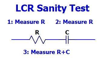
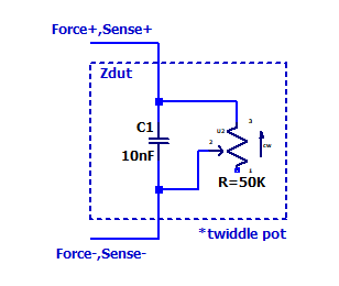
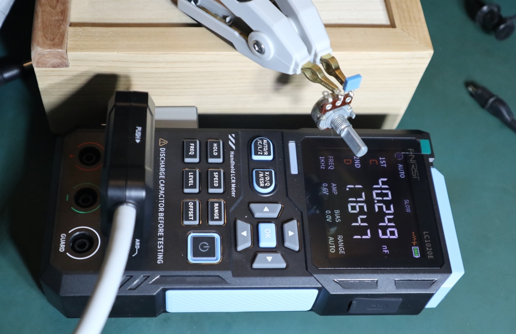
To test the responsiveness of my new LCR meter, I soldered a 10 nF capacitor in parallel with a 50 kOhm potentiometer (configured as a rheostat) and twiddled the potentiometer shaft.
I used the 4-wire kelvin clips (which work great btw) and configured the meter to auto-identify and auto-range with a test frequency of 1 kHz.
Here is a video of display updating
The measurement update rate and identification time is more than fast enough for my needs. Once the meter settles on a range and component type, it reverts to a slow update speed (presumably it is average a few readings together too, but I don’t know).
I don’t understand how the “auto” series vs parallel readout works, there is no noticeable annunciation indicating which calculation it is using. So, I would recommend manually choosing a topology yourself, in the video I had the meter in “series” mode.
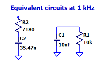
The capacitance changing with resistance is the correct result for the series readout mode in the video. The two circuits below are equivalent at 1kHz
This is significantly faster than most equivalently priced DMMs auto ranging performance on DC volts or resistance. It is also what I would expect of a product in 2025 having a 32-bit MCU with floating point hardware running at tens of megahertz.
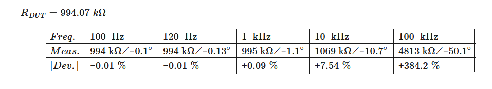
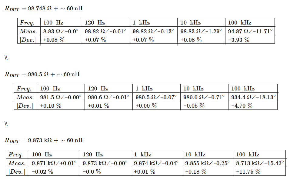
It is unfortunate the measurement performance at 100 kHz is so lousy, otherwise it would be easy to recommend the meter for the price.