Table of contents
Abstract
Who doesn't like LEDs? So, another LED matrix panel.
Project
Hello everyone!
I would like to show you a LED matrix circuit that you can use to display cheers in a more animated way, maybe this way you will delight Santa Claus even more. (
) Or, show your work and creativity and receive the much-desired gifts. (
)
I recovered 3x Kingbright TC24-11SRWA (2005-01) matrices from an elevator panel, to these I added another Kingbright TC24-11SRWA (2005-33). The idea has been "standing" for a long time, it is in progress, I would need one more piece, I found it on a website but it costs me as much as a new 8x32 panel, and I want to keep the costs low, also I am not pressed for time.
So, short BoM:
- 4x 5x8 LED matrices;
- 4x MAX7219;
- similar board with Arduino Nano;
- 5V power supply;
- and some coding of course.
The 5x8 LED matrix panel
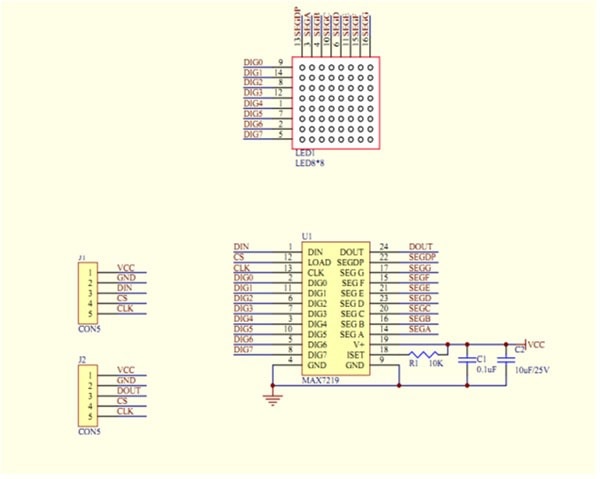
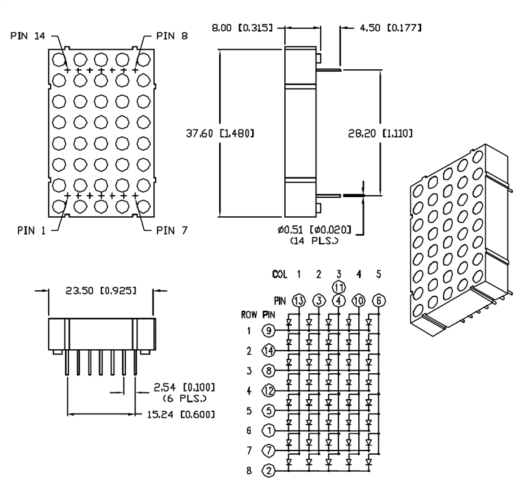
Below we have a typical circuit for MAX7219+8x8 LED matrix, this is the beginning, further I looked for a datasheet for 5x8 LED matrix.
| {gallery}My Gallery Title |
|---|
|
Typical MAX7219+MAX7219 circuit |
|
5x8 LED matrix pinout |
Then I multiplied the circuit to make an 8x20 panel: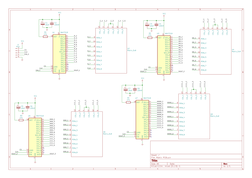
BoM:
"Component Count:" "21"
"Ref" "Value"
"C1" "10uF"
"C2" "100nF"
"C3" "10uF"
"C4" "100nF"
"C5" "10uF"
"C6" "100nF"
"C7" "10uF"
"C8" "100nF"
"J1" "Pins"
"R1" "27k"
"R2" "27k"
"R3" "27k"
"R4" "27k"
"U1" "MAX7219"
"U2" "Matrix_5x8"
"U3" "MAX7219"
"U4" "Matrix_5x8"
"U5" "MAX7219"
"U6" "Matrix_5x8"
"U7" "MAX7219"
"U8" "Matrix_5x8"
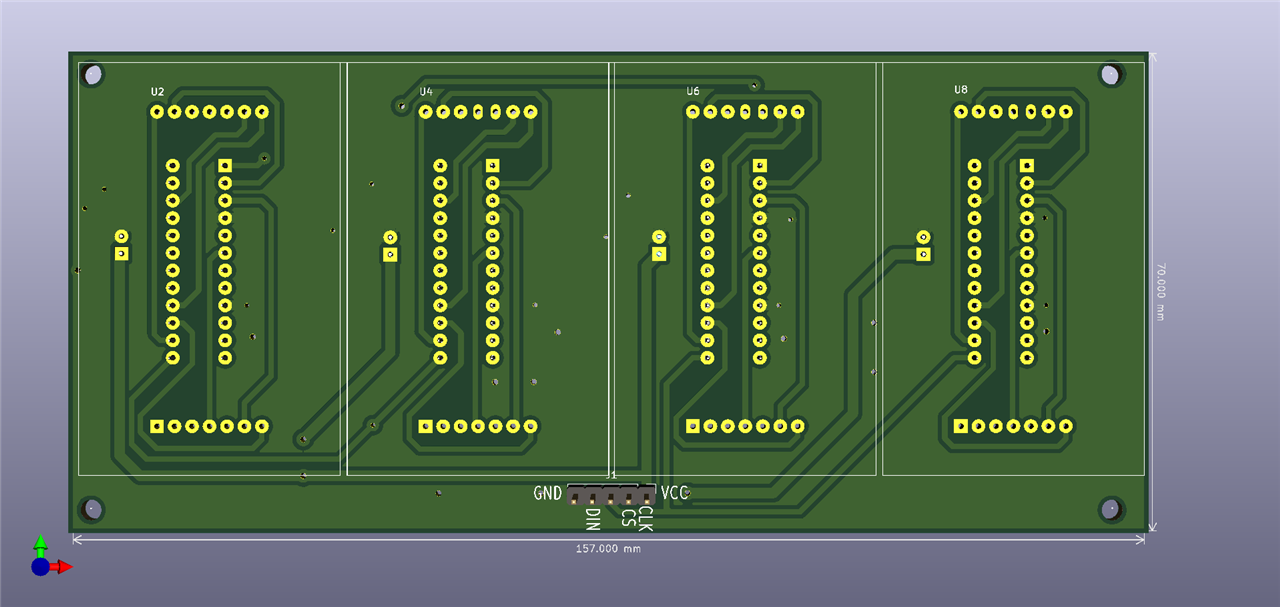
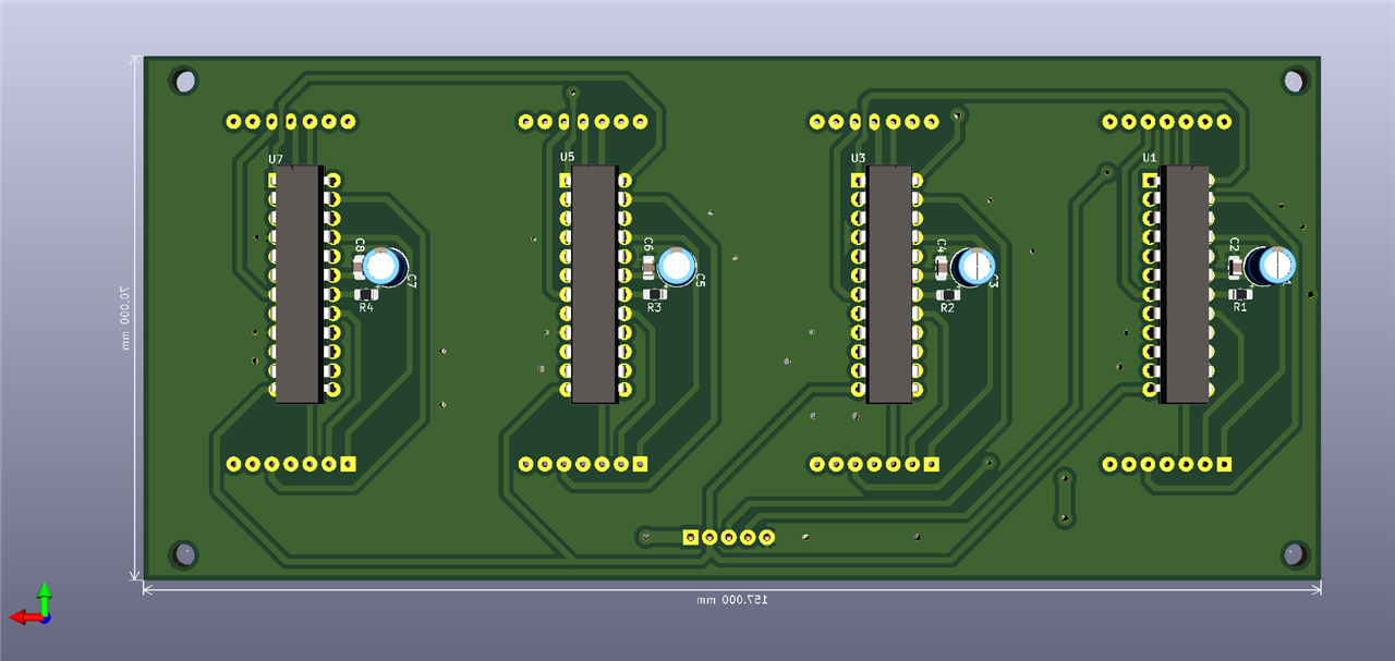
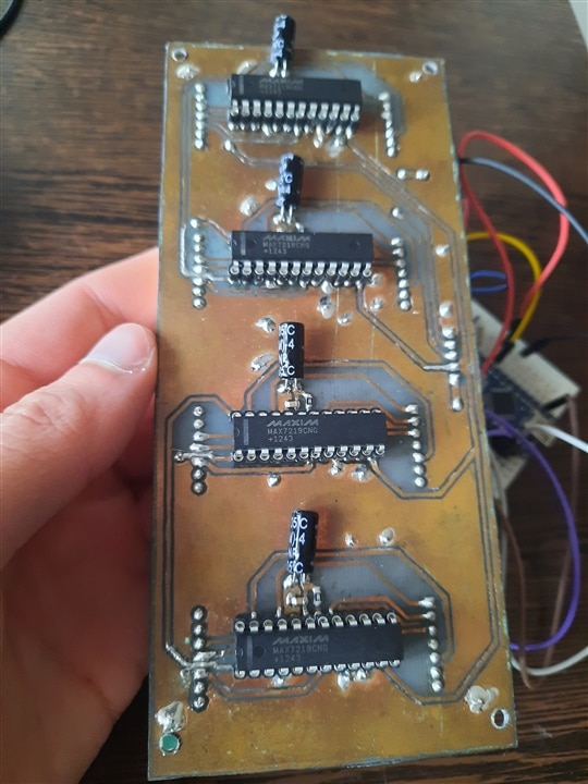
I think you recognize the program I used to make the PCB, KiCAD. It's a double-layer PCB, which I made in a homemade way, using the thermal toner transfer method. It took me several tries, but I got a product that I can use, and despite its condition (the copper surface is visibly damaged) it's still fine. I also had to resort to "vias" (I used terminals from TH resistors ).
Fast forward to the description of the homemade PCB manufacturing process:
1. I clean the copper surface very well;
2. I print the "drawing" on a magazine sheet, or photo sheet (with a laser printer);
3. I heat an iron for a few minutes;
4. I place the sheet over the copper plate and position the iron over the sheet, about 2 minutes should be enough. If touch-ups are needed, I use a permanent marker.
5. For the other layer, I drilled 4 holes in the board, in the corners, as well as in the sheet, and "sewn" them with a thin copper wire until they overlapped (definitely not perfectly, but I had a very small deviation).
6. Using ferric chloride, I corroded the board.
I don't have pictures or videos of the process, I did that a long time ago, in the meantime I found another method, which will definitely make my work easier. It is the hardest homemade PCB I have ever made and I feel like laughing when I see what madness went through my head () but at the same time I am delighted with the success (
).
I will try to clean the PCB more, then apply a layer of transparent silicone spray. On the one hand I was not sure of the success, on the other hand I choose to experiment on a circuit/test board before manufacturing a PCB at a manufacturer. Maybe by Christmas 2025 I will complete it with the remaining parts.
When I have the fifth matrix I will look to redo the PCB so that it no longer degrades aesthetically.
| {gallery}My Gallery Title |
|---|
|
Top PCB |
|
Bottom PCB |
|
|
|
|
Power supply
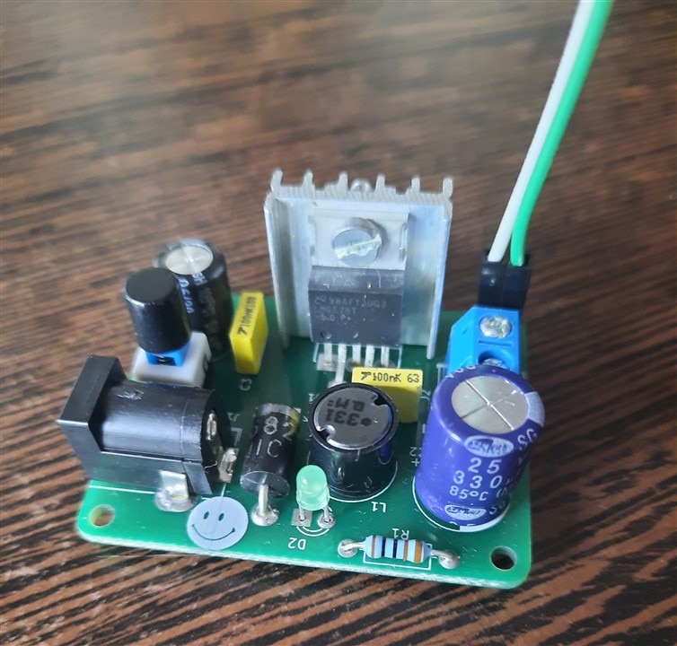
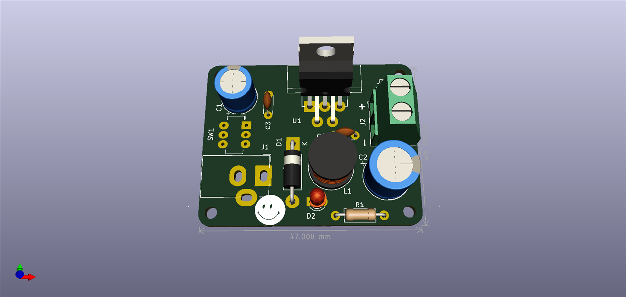
I have previously made some PCBs for LM2575 which give me 5V DC, and I have a 9V adapter at the input. It is a switching power supply and I use it as a step-down from 9V or 12V to 5V.
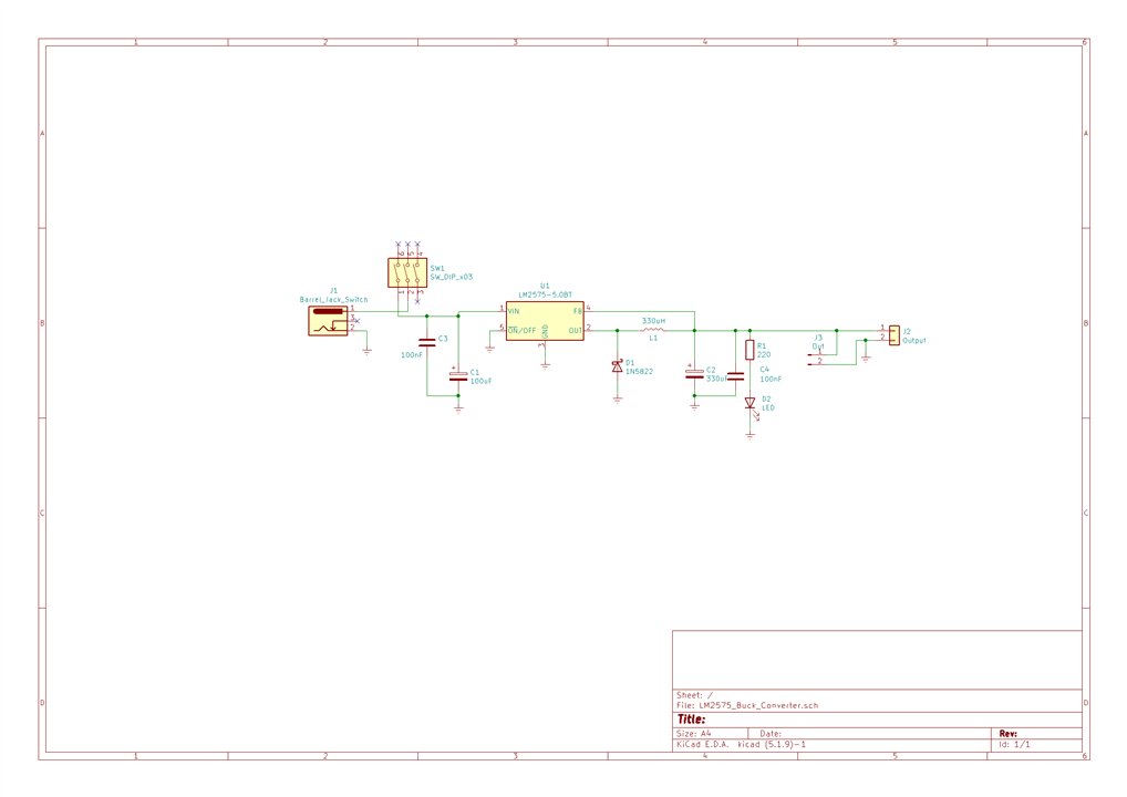
I am also attaching a circuit for those who need it:
| {gallery}My Gallery Title |
|---|
|
LM2575 buck converter |
|
LM2575 PCB |
|
|
BoM:
"Tool:" "Eeschema (5.1.9)-1"
"Component Count:" "13"
"Ref" "Value"
"C1" "100uF"
"C2" "330uF"
"C3" "100nF"
"C4" "100nF"
"D1" "1N5822"
"D2" "LED"
"J1" "Barrel_Jack_Switch"
"J2" "Output"
"J3" "Out"
"L1" "330uH"
"R1" "220"
"SW1" "SW_DIP_x03"
"U1" "LM2575-5.0BT"
The microcontroller is an ATMega328p, and we also need the Arduino IDE.
Coding
I had trouble "matching" my circuit to what is exemplified by the sketches in the Arduino IDE.
The small key changes in a random sketch:
1. #define HARDWARE_TYPE MD_MAX72XX::DR0CR0RR0_HW
I'm looking for this line to change to DR0CR0RR0_HW which corresponds to my array type.
2. #define MAX_DEVICES 4
I also have 4 arrays, but it's worth mentioning in case you have a different one.
3. #define CHAR_SPACING 1
Where 1 represents dots spacing between characters.
4. In the MD_MAX72XX library, look for MD_MAX72xx.cpp, which we can open with Notepad++, and in which we look for:
// Display parameter constants
// Defined values that are used throughout the library to define physical limits
#define ROW_SIZE 8 ///< The size in pixels of a row in the device LED matrix array
#define COL_SIZE 5 ///< The size in pixels of a column in the device LED matrix array
I need to change COL_SIZE from 8 to 5.
These are the changes that were necessary in advance. Thanks to tipppo for his help.
Now, I used the "MD_MAX72xx_Message_Serial_Scrolling" sketch from the Arduino IDE, in which I wrote my message: uint8_t curMessage[BUF_SIZE] = { "Happy Holidays e14! " };// Use the MD_MAX72XX library to scroll text on the display
//
// Demonstrates the use of the callback function to control what
// is scrolled on the display text.
//
// User can enter text on the serial monitor and this will display as a
// scrolling message on the display.
// Speed for the display is controlled by a pot on SPEED_IN analog in.
//
#include <MD_MAX72xx.h>
#include <SPI.h>
#define IMMEDIATE_NEW 0 // if 1 will immediately display a new message
#define USE_POT_CONTROL 1
#define PRINT_CALLBACK 0
#define PRINT(s, v) { Serial.print(F(s)); Serial.print(v); }
// Define the number of devices we have in the chain and the hardware interface
// NOTE: These pin numbers will probably not work with your hardware and may
// need to be adapted
#define HARDWARE_TYPE MD_MAX72XX::DR0CR0RR0_HW // ****************************
#define MAX_DEVICES 4 // *******************************
#define CLK_PIN 13 // or SCK
#define DATA_PIN 11 // or MOSI
#define CS_PIN 10 // or SS
// SPI hardware interface
MD_MAX72XX mx = MD_MAX72XX(HARDWARE_TYPE, CS_PIN, MAX_DEVICES);
// Arbitrary pins
//MD_MAX72XX mx = MD_MAX72XX(HARDWARE_TYPE, DATA_PIN, CLK_PIN, CS_PIN, MAX_DEVICES);
// Scrolling parameters
#if USE_POT_CONTROL
#define SPEED_IN A5 // ***********************************
#else
#define SCROLL_DELAY 75 // in milliseconds
#endif // USE_POT_CONTROL
#define CHAR_SPACING 1 // pixels between characters ***************************
// Global message buffers shared by Serial and Scrolling functions
#define BUF_SIZE 75
uint8_t curMessage[BUF_SIZE] = { "Happy Holidays e14! " };//********************
uint8_t newMessage[BUF_SIZE];
bool newMessageAvailable = false;
uint16_t scrollDelay; // in milliseconds
void readSerial(void)
{
static uint8_t putIndex = 0;
while (Serial.available())
{
newMessage[putIndex] = (char)Serial.read();
if ((newMessage[putIndex] == '\n') || (putIndex >= BUF_SIZE - 3)) // end of message character or full buffer
{
// put in a message separator and end the string
newMessage[putIndex++] = ' ';
newMessage[putIndex] = '\0';
// restart the index for next filling spree and flag we have a message waiting
putIndex = 0;
newMessageAvailable = true;
}
else if (newMessage[putIndex] != '\r')
// Just save the next char in next location
putIndex++;
}
}
void scrollDataSink(uint8_t dev, MD_MAX72XX::transformType_t t, uint8_t col)
// Callback function for data that is being scrolled off the display
{
#if PRINT_CALLBACK
Serial.print("\n cb ");
Serial.print(dev);
Serial.print(' ');
Serial.print(t);
Serial.print(' ');
Serial.println(col);
#endif
}
uint8_t scrollDataSource(uint8_t dev, MD_MAX72XX::transformType_t t)
// Callback function for data that is required for scrolling into the display
{
static uint8_t* p = curMessage;
static enum { NEW_MESSAGE, LOAD_CHAR, SHOW_CHAR, BETWEEN_CHAR } state = LOAD_CHAR;
static uint8_t curLen, showLen;
static uint8_t cBuf[15];
uint8_t colData = 0; // blank column is the default
#if IMMEDIATE_NEW
if (newMessageAvailable) // there is a new message waiting
{
state = NEW_MESSAGE;
mx.clear(); // clear the display
}
#endif
// finite state machine to control what we do on the callback
switch (state)
{
case NEW_MESSAGE: // Load the new message
memcpy(curMessage, newMessage, BUF_SIZE); // copy it in
newMessageAvailable = false; // used it!
p = curMessage;
state = LOAD_CHAR;
break;
case LOAD_CHAR: // Load the next character from the font table
showLen = mx.getChar(*p++, sizeof(cBuf) / sizeof(cBuf[0]), cBuf);
curLen = 0;
state = SHOW_CHAR;
// if we reached end of message, opportunity to load the next
if (*p == '\0')
{
p = curMessage; // reset the pointer to start of message
#if !IMMEDIATE_NEW
if (newMessageAvailable) // there is a new message waiting
{
state = NEW_MESSAGE; // we will load it here
break;
}
#endif
}
// !! deliberately fall through to next state to start displaying
case SHOW_CHAR: // display the next part of the character
colData = cBuf[curLen++];
if (curLen == showLen)
{
showLen = CHAR_SPACING;
curLen = 0;
state = BETWEEN_CHAR;
}
break;
case BETWEEN_CHAR: // display inter-character spacing (blank columns)
colData = 0;
curLen++;
if (curLen == showLen)
state = LOAD_CHAR;
break;
default:
state = LOAD_CHAR;
}
return (colData);
}
void scrollText(void)
{
static uint32_t prevTime = 0;
// Is it time to scroll the text?
if (millis() - prevTime >= scrollDelay)
{
mx.transform(MD_MAX72XX::TSL); // scroll along - the callback will load all the data
prevTime = millis(); // starting point for next time
}
}
uint16_t getScrollDelay(void)
{
#if USE_POT_CONTROL
uint16_t t;
t = analogRead(SPEED_IN);
t = map(t, 0, 1023, 25, 250);
Serial.println(t);
return (t);
#else
return (SCROLL_DELAY);
#endif
}
void setup()
{
mx.begin();
mx.setShiftDataInCallback(scrollDataSource);
mx.setShiftDataOutCallback(scrollDataSink);
#if USE_POT_CONTROL
pinMode(SPEED_IN, INPUT);
#else
scrollDelay = SCROLL_DELAY;
#endif
newMessage[0] = '\0';
Serial.begin(57600);
Serial.print("\n[MD_MAX72XX Message Display]\nType a message for the scrolling display\nEnd message line with a newline");
}
void loop()
{
scrollDelay = getScrollDelay();
readSerial();
scrollText();
}
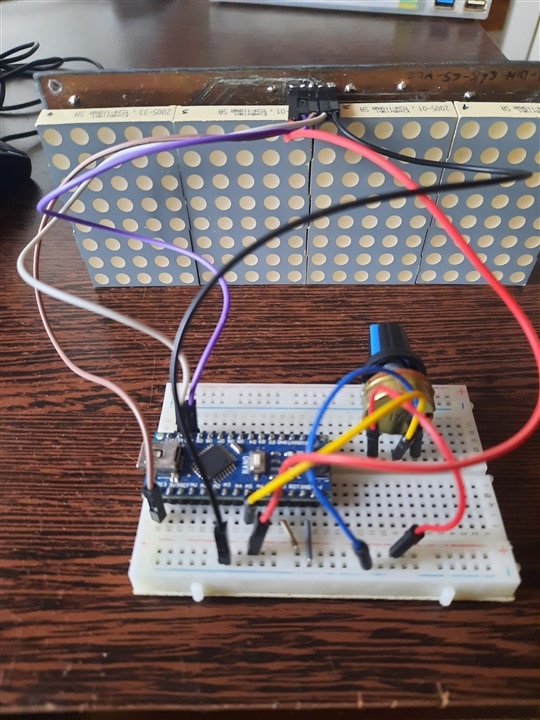
We have a text message that is displayed on the panel by scrolling, and from a 5kΩ potentiometer I can adjust the speed. The circuit is simple, I made it on a breadboard, we also have a video below: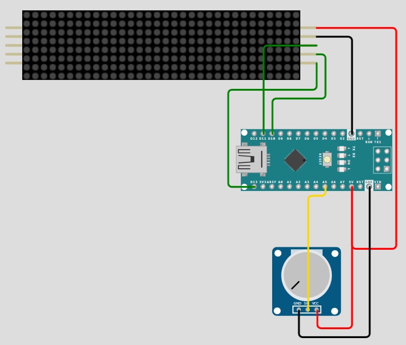
Maybe this information will be useful for others who experiment with MAX7219 and different LED matrices. Furthermore, by adding a Bluetooth HC-05 module you can change the text you want to display at any time, and you still need an application on your phone.
The work is not finished, a 3D enclosure would also work, maybe I can manage to do something. So it remains a work in progress...
What do you think? What is your best cheer? Or what is the longest wish? By the time Santa Claus reads it to the end he falls asleep.
Thank you!
May 2025 bring you everything that is better and what you wish for.


