

Table of contents

Abstract
The holidays are a time of creativity, and this year I wanted to capture that spirit in an electronics project that I use every day. The FestiveBoard is a specially designed mechanical keyboard with dynamic, holiday-themed lighting that transforms it into a seasonal celebration, symbolizing Christmas, Hanukkah, and Winter.
Project
Introduction
This year, I wanted to make an electronics project that I use daily to reflect the creative, cozy, and expressive nature of the holidays. This is a specially designed mechanical keyboard with dynamic holiday-themed lighting that turns it into a seasonal celebration. Rather than just typing on this keyboard, one will find themselves immersed in holiday-themed RGB light shows that are designed for Christmas celebrations, Hanukkah events, New Year's firework displays, as well as for Relaxed Winter Nights. For me, holidays are about joy, creativity, and creating meaningful things, and this project uses electronics, light, and programming to make that feeling come to life.
Project Design
Schematic Design
My design journey began with the PCB. Whenever I design a PCB, I always focus not only on functionality but also on its artistic appearance. For most of my projects, I use EasyEDA as my primary PCB design tool. When I decided to build a mechanical keyboard completely from scratch, I started by researching existing designs. I found many open-source keyboard projects online, but none of them felt quite right to adopt directly. So, I chose to create my own custom design from the ground up.
Although most community designs are based on KiCad, I was more comfortable working in EasyEDA, so I continued with that platform. However, this came with its own challenges. When I began designing, I couldn’t find any complete switch footprint in EasyEDA that included both the required mechanical cutouts and the electrical pads together. Since I wanted the keyboard to support hot-swappable switches, I searched the EasyEDA library and fortunately, found some hot-swap socket footprints. I selected one and then modified it to make it compatible with MX-style switches, paving the way for my fully custom keyboard PCB.
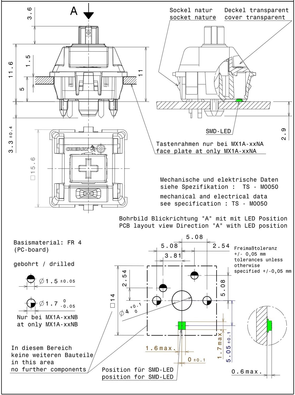
Based on the measurement of the switch, I carefully adjusted the pad placement to support hot-swappable sockets and added the required mechanical cutouts to ensure proper switch fitment. This step was critical, as the footprint directly affects both mechanical compatibility and electrical reliability. Once finalized, this custom footprint became the foundation for my entire key matrix.
The following image shows the mechanical measurement of a common Cherry MX switch.
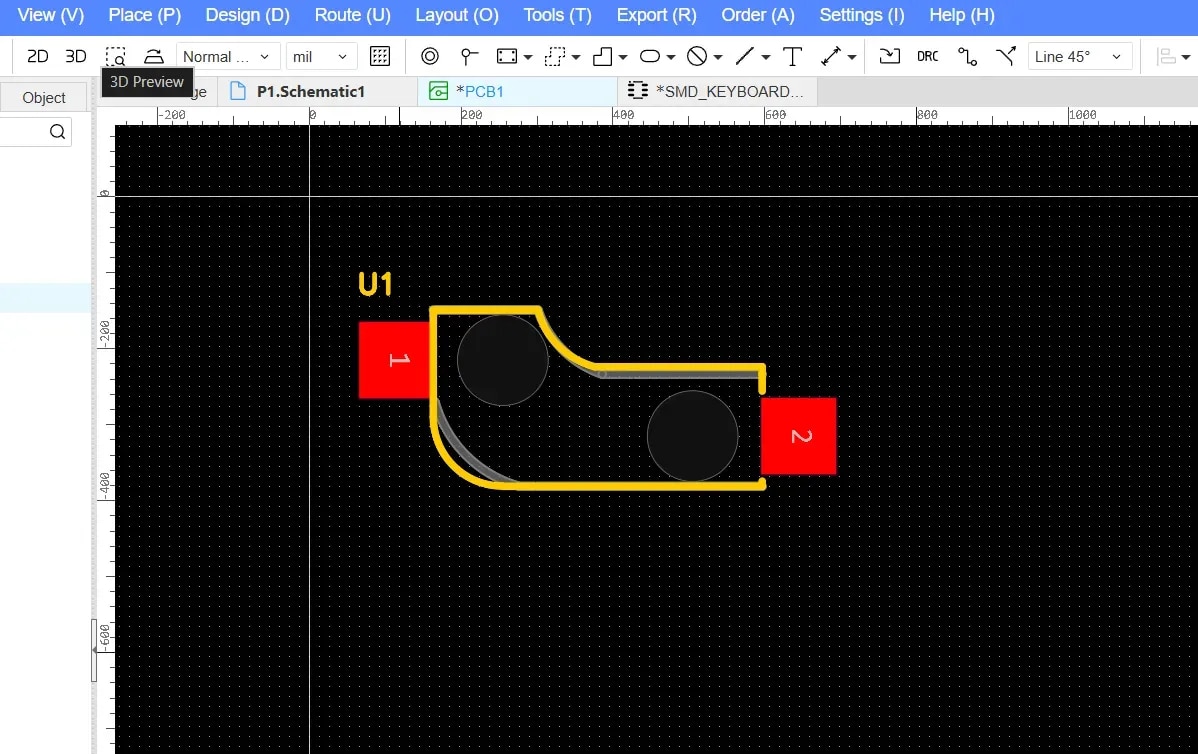
Below is the available footprint for the mechanical key switch.
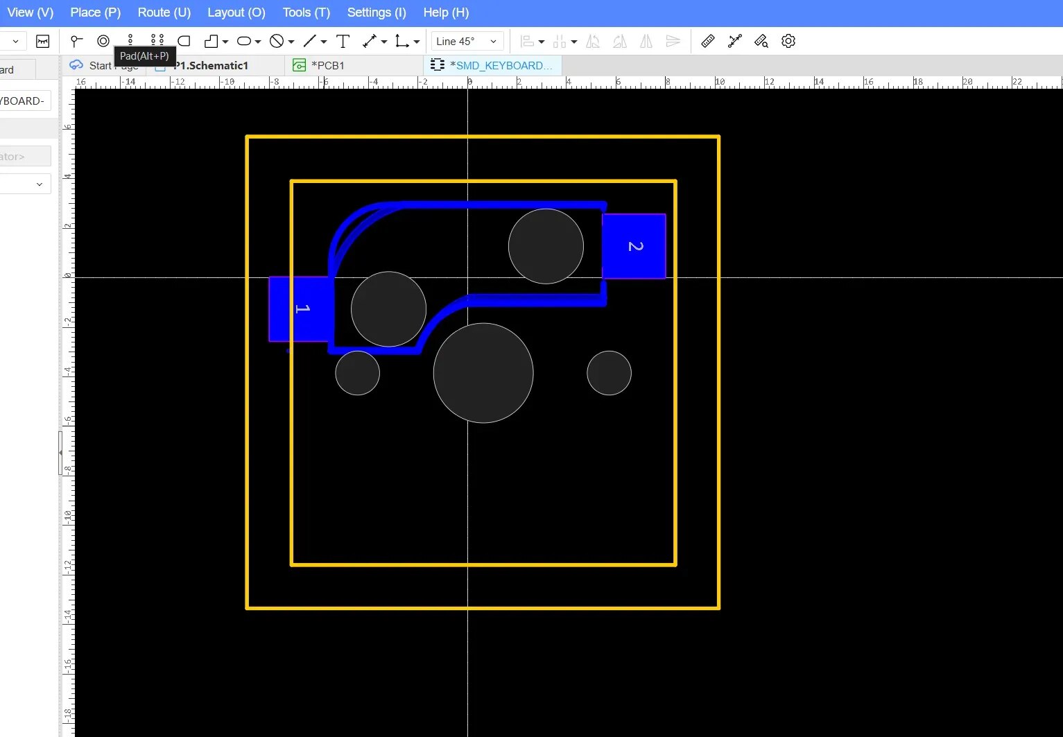
I modified the original footprint to match the design shown below.
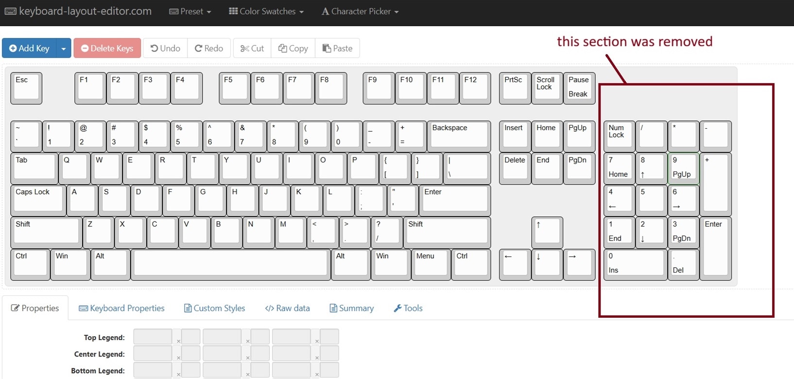
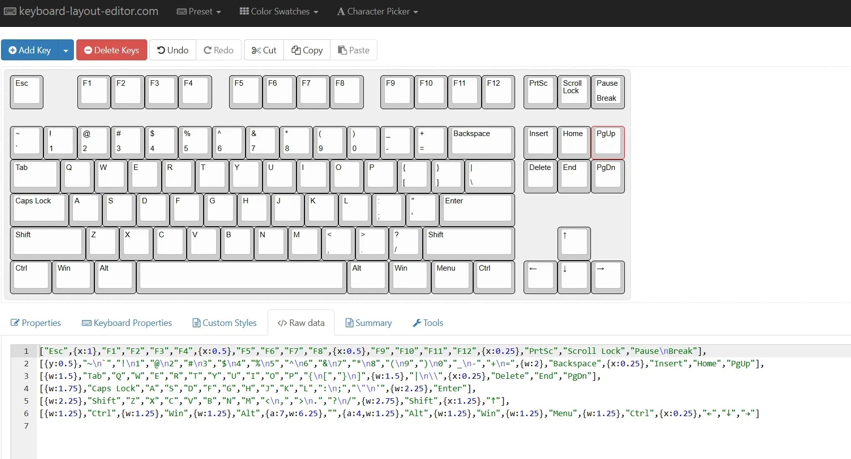
To design the complete schematic, a proper keyboard layout was essential. I used keyboard-layout-editor.com to explore different preset layouts, and the ANSI 104 layout immediately caught my attention. Although it is a full-sized 100% keyboard, I wanted something slightly more compact. Since I am not a heavy user of the numeric keypad, I decided to remove that section and convert the design into a Tenkeyless (TKL) layout, making the keyboard more practical and space-efficient while still retaining the essential keys.
The layout consists of 87 keys, I added all 87 switches to the schematic and organized them into a matrix configuration. As shown in the screenshot, the keys are arranged across six rows and fourteen columns, reflecting the logical structure of the key matrix used for scanning and firmware mapping.
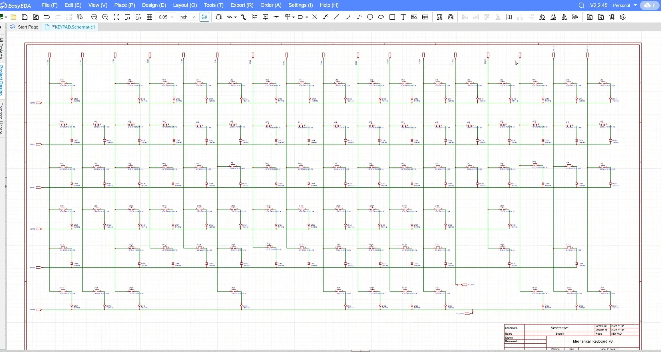
The row–column structure was chosen not only to reduce pin usage but also to keep the matrix logically organized and easy to route on the PCB. Grouping keys in this way helped maintain clean schematic organization and later simplified both PCB routing and firmware configuration.
To prevent ghosting and ensure reliable key detection, I added a signal diode for every switch, oriented from the column to the row. This diode-per-key configuration allows proper current flow during matrix scanning and enables full n-key rollover.
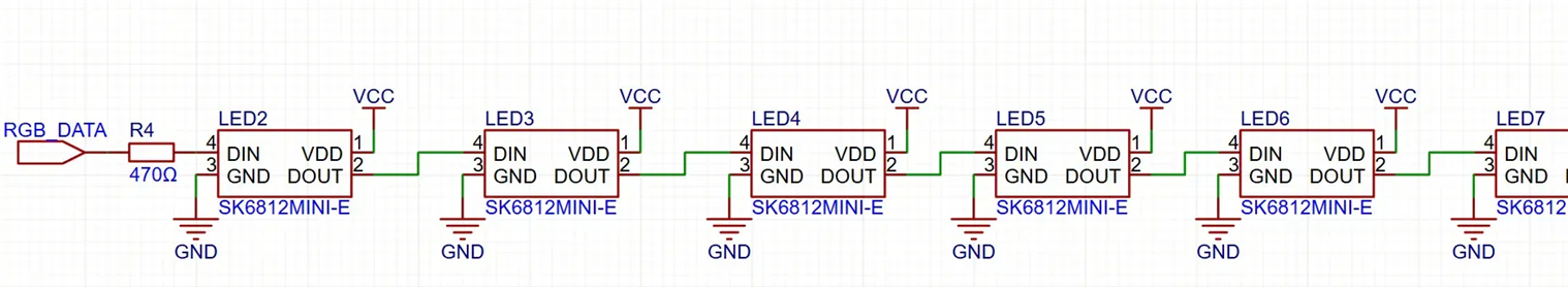
One of the key focuses of this keyboard is the RGB lighting, as it will be used to display the holiday-themed animations. To achieve this, I selected 87 RGB LEDs for the 87 keys, ensuring every key can participate in the lighting effects. In addition, I added 6 extra decorative LEDs to enhance the overall festive appearance and indicate the mode of the keyboard.
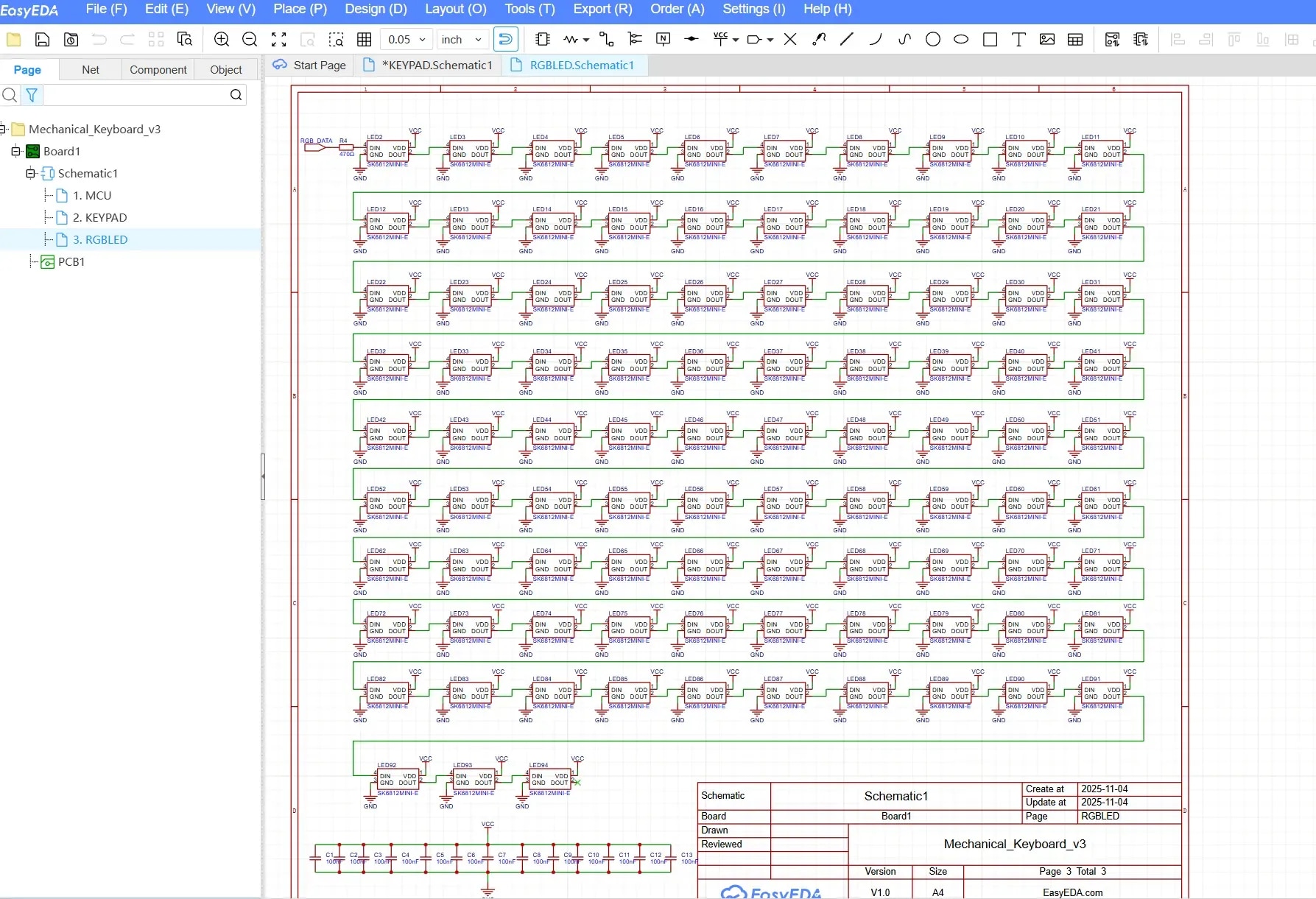
All RGB LEDs are controlled through a single daisy-chained data line, which simplifies both PCB routing and firmware implementation. As per the datasheet recommendation, a 470 Ω series resistor was added to the RGB data line. This resistor helps reduce signal ringing and current spikes, particularly at higher data rates, ensuring more reliable communication between the microcontroller and the LED chain.
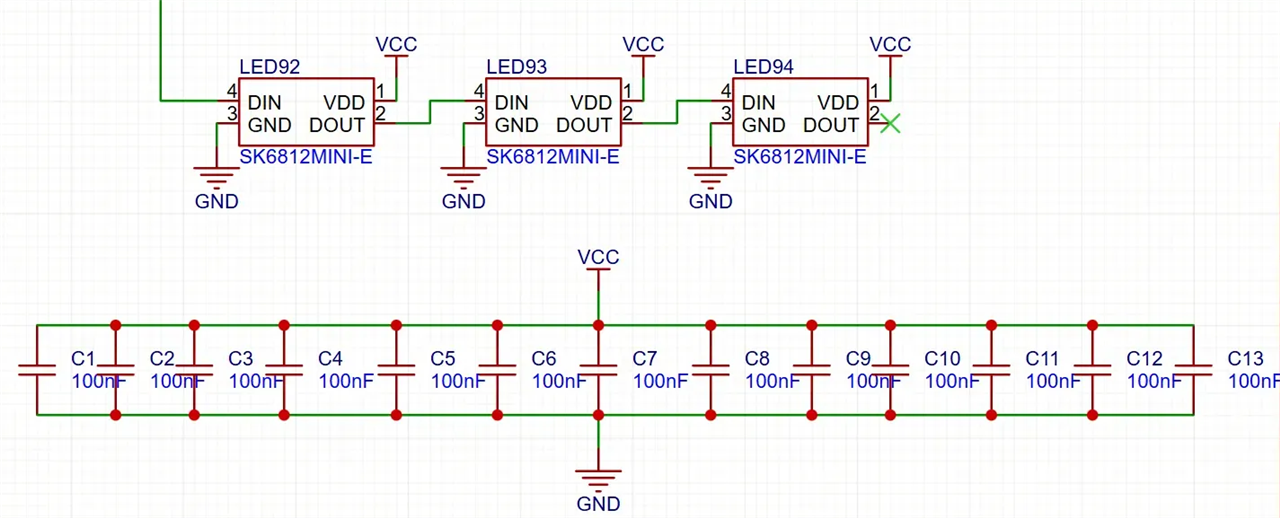
Special attention was also given to power distribution and decoupling. Multiple decoupling capacitors were placed across the RGB power rail to stabilize the supply voltage when a large number of LEDs are active simultaneously. These capacitors help prevent voltage drops, flickering, and electrical noise that could otherwise affect LED performance or interfere with other parts of the system. Though it is recommended to use one capacitor with each LEDs, to keep it simple I used one for multiple LEDs. I used total 13 for 96 LEDs.
A 128×32 OLED display was added to the design to provide real-time visual feedback, such as active layers, animation type, RGB brightness, and system status. For the main controller, I chose the Raspberry Pi Pico, as it is highly maker-friendly, powerful, and well-supported. Although the official Raspberry Pi Pico board uses a Micro-USB connector, I incorporated a USB Type-C port for my design for improved durability, reversibility, and compatibility with modern devices. I also incorporated a rotary encoder in my design.

PCB Design
Unlike conventional keyboards that use a single PCB for component placement and separate metal plates for key holding, my keyboard was designed as a three-layer PCB structure, where each layer serves both as a functional unit and an aesthetic purpose. This layered approach allowed me to blend electrical design, mechanical structure, and visual storytelling into a single cohesive system.
The bottom PCB layer hosts all electronic components, including switches, diodes, RGB LEDs, the Raspberry Pi Pico, OLED display, rotary encoder, power LED, reset button, and USB Type-C connector. The second layer functions as the plate, providing mechanical support for the switches, while the third layer (top case) acts as the frame, defining the overall shape and rigidity of the keyboard. Together, these layers form a stacked structure that is both structurally sound and visually expressive.
To ensure accurate and standard-compliant switch placement, I generated a DXF layout file from Swill’s Keyboard Plate Builder (http://builder.swillkb.com/). To do this, I copied Raw Data from Keyboard Layout Editor (KLE) (https://www.keyboard-layout-editor.com/) for my selected ANSI 104-key layout without the numeric keypad as showen the image below.
Then I pasted the row data into Swill’s Keyboard Plate Builder (http://builder.swillkb.com/) for generating the DXF based on the layout as shown in the image below.

I also generated a top layer (top case) from the swillkb builder site.
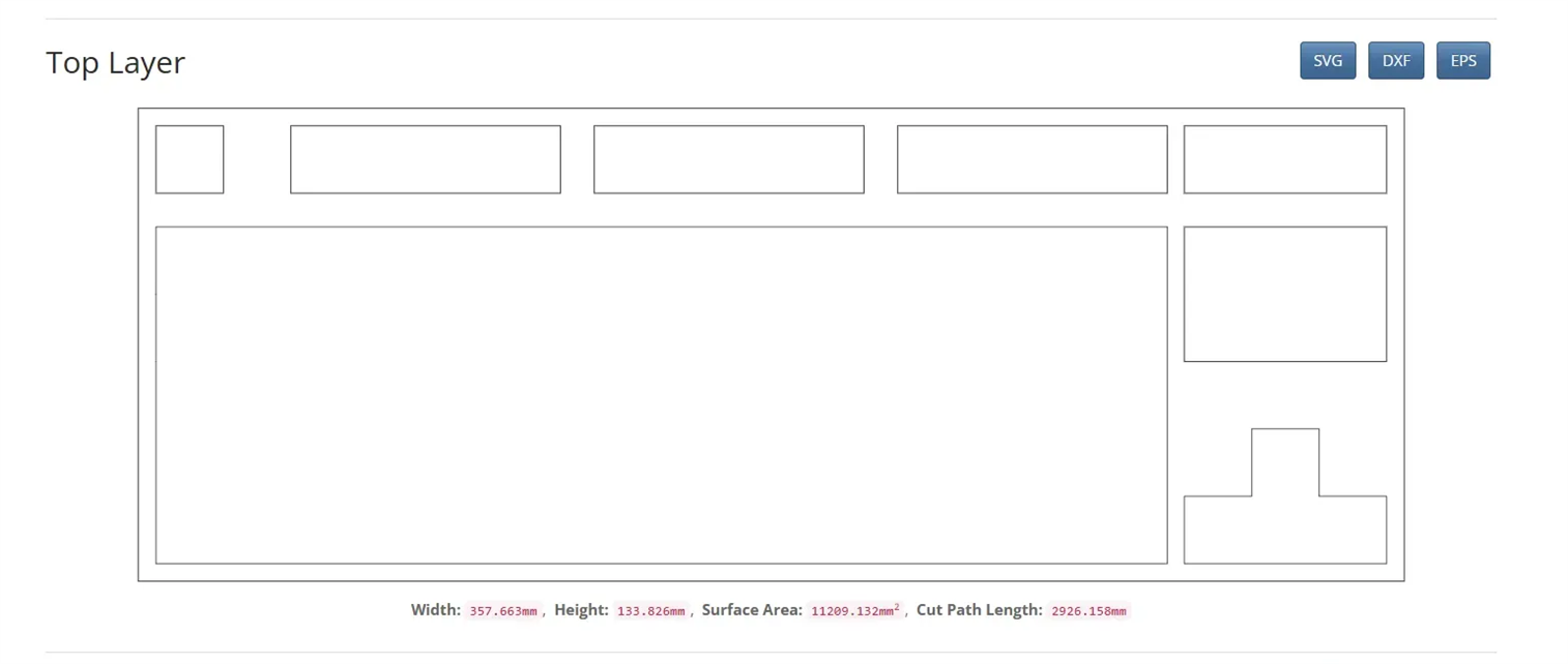
I downloaded the DFX files for both layers. I then imported these DXF files into EasyEDA, where they served as an exact reference for placing every key switch footprint on the PCB. These layout images ensured consistent key spacing, perfect alignment, and compatibility with standard mechanical keycaps, while also significantly reducing placement errors.
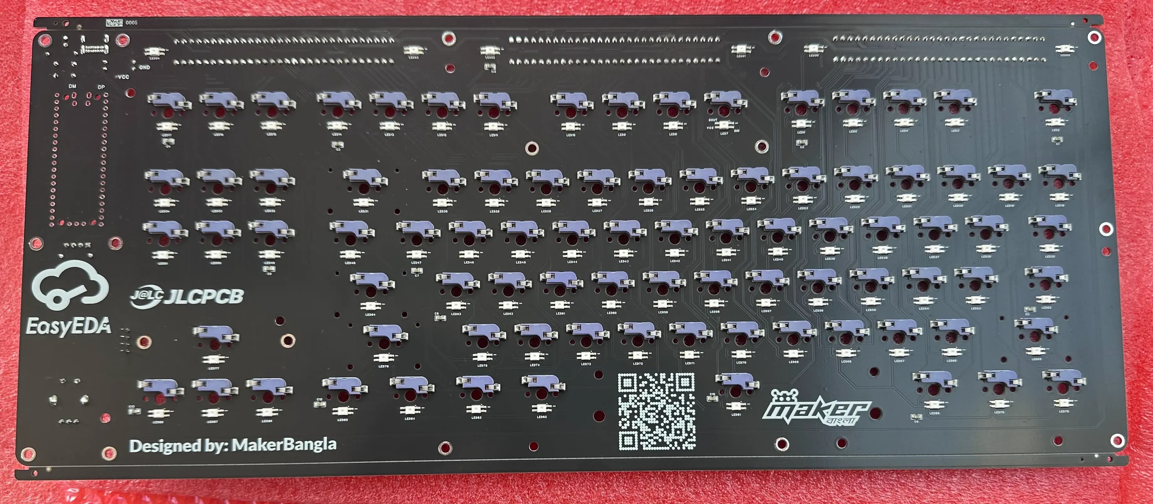
After placing the switches, I started working with other components. Every key in the keyboard uses a dedicated diode to prevent ghosting, but instead of placing the diodes close to individual switches as is commonly done, I intentionally treated them as a visual design feature. I placed all diodes parallel on the top side of the PCB, aligned them straight, and divided them into three distinct sections across the PCB. Without hiding them, I intentionally keep them visible purely for aesthetic reasons. Care was taken to ensure that this arrangement did not negatively impact routing or electrical performance. I placed six additional addressable RGB LEDs within these diode sections, one LED on each side of every diode group. When illuminated, these LEDs frame the diode lines with light, emphasizing symmetry and creating a striking visual contrast against the PCB surface.
I placed the Raspberry Pi Pico prominently on the right side of the PCB rather than being hidden to give a strong DIY look. A matching window was added to the plate layer, allowing the Pico to remain fully visible after assembly. A USB Type-C connector was placed in the top-right corner for modern connectivity and ease of access. Below the Pico, a 128×32 OLED display was positioned to present layer status and system information. Finally, the rotary encoder was placed in the bottom-right corner, providing intuitive physical control without interfering with the main typing area.
To maintain the PCB's cleanliness, accessibility, and aesthetic coherence, I positioned all components carefully, considering usability, routing simplicity, and visual balance. This PCB design reflects my belief that hardware does not need to be hidden to be beautiful.
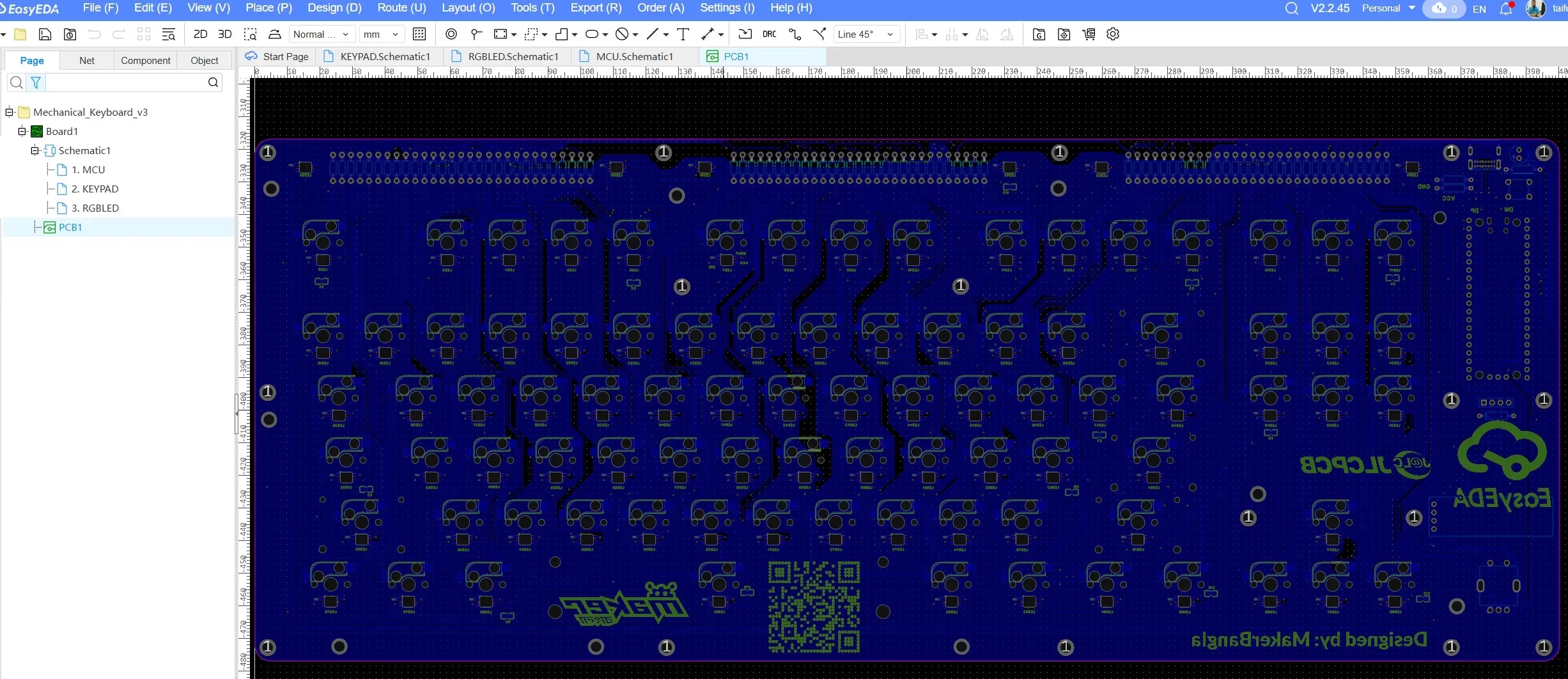
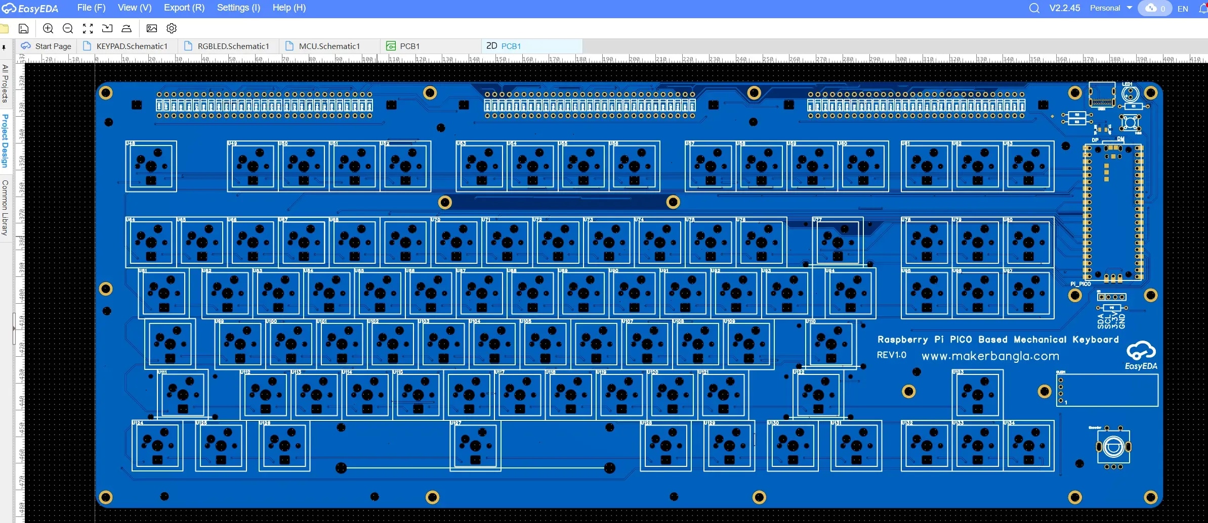
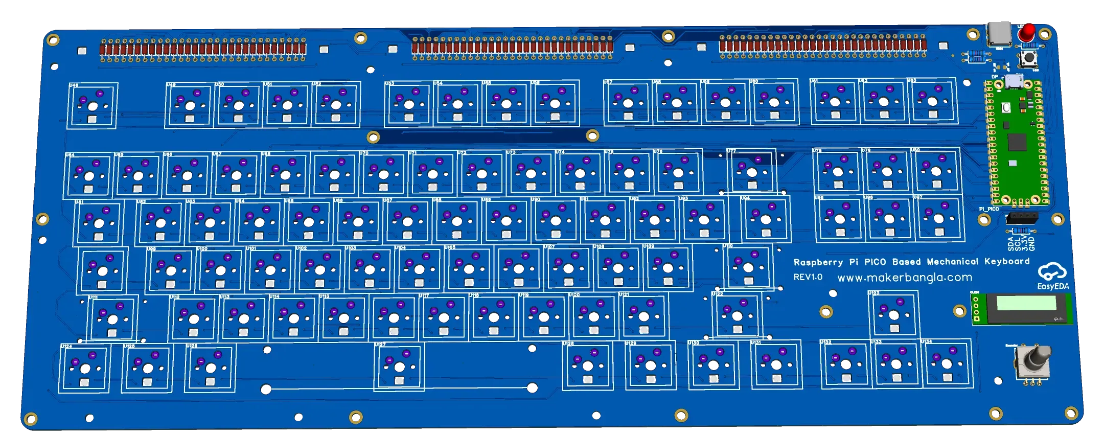
After finishing component placement and routing, the PCB layout appears as shown below.
Top layer of base PCB:

Bottom layer:
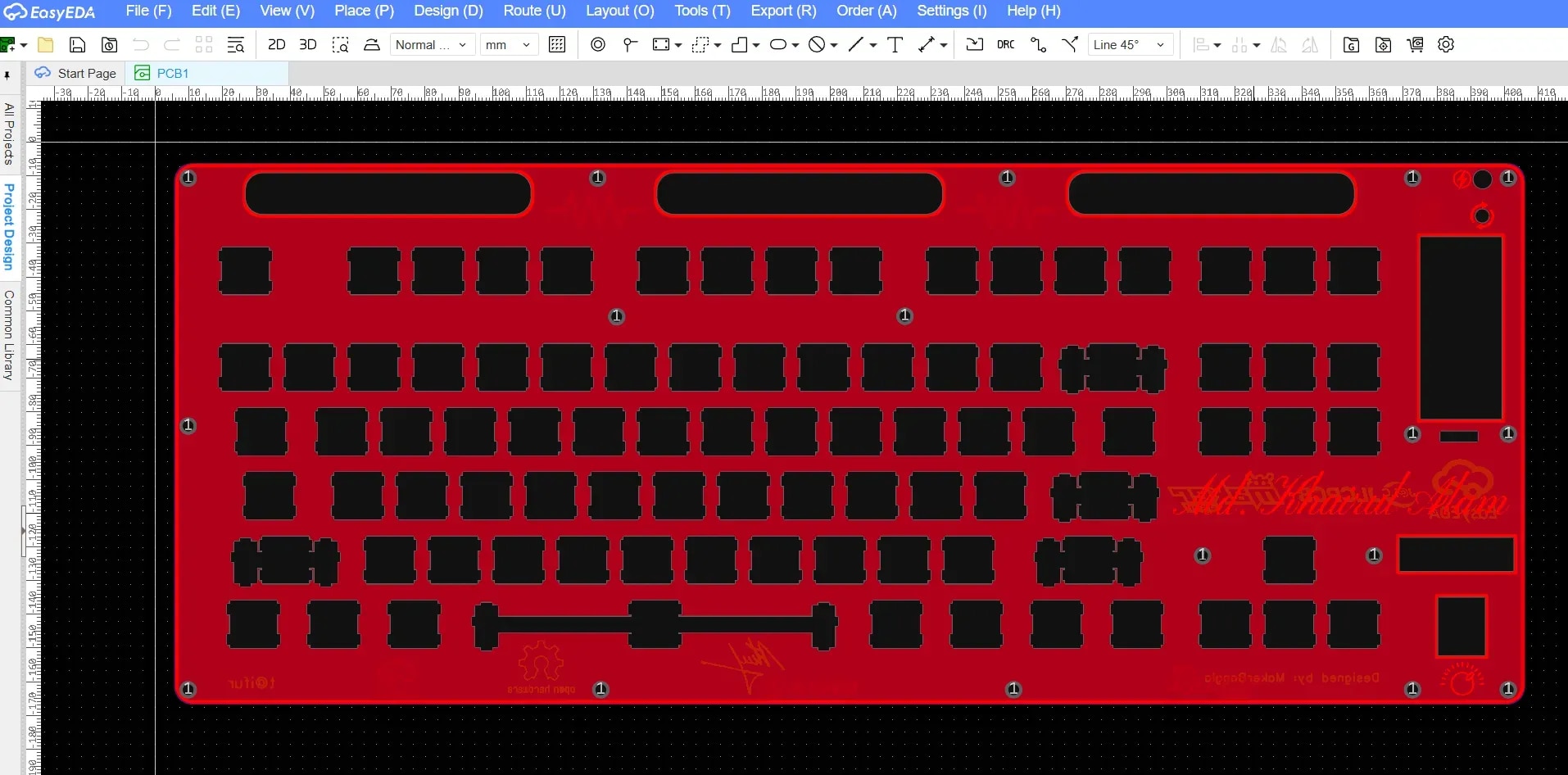
2D View of the layout:
3D View (top side):
3D View (bottom side):

Plate and Frame Design
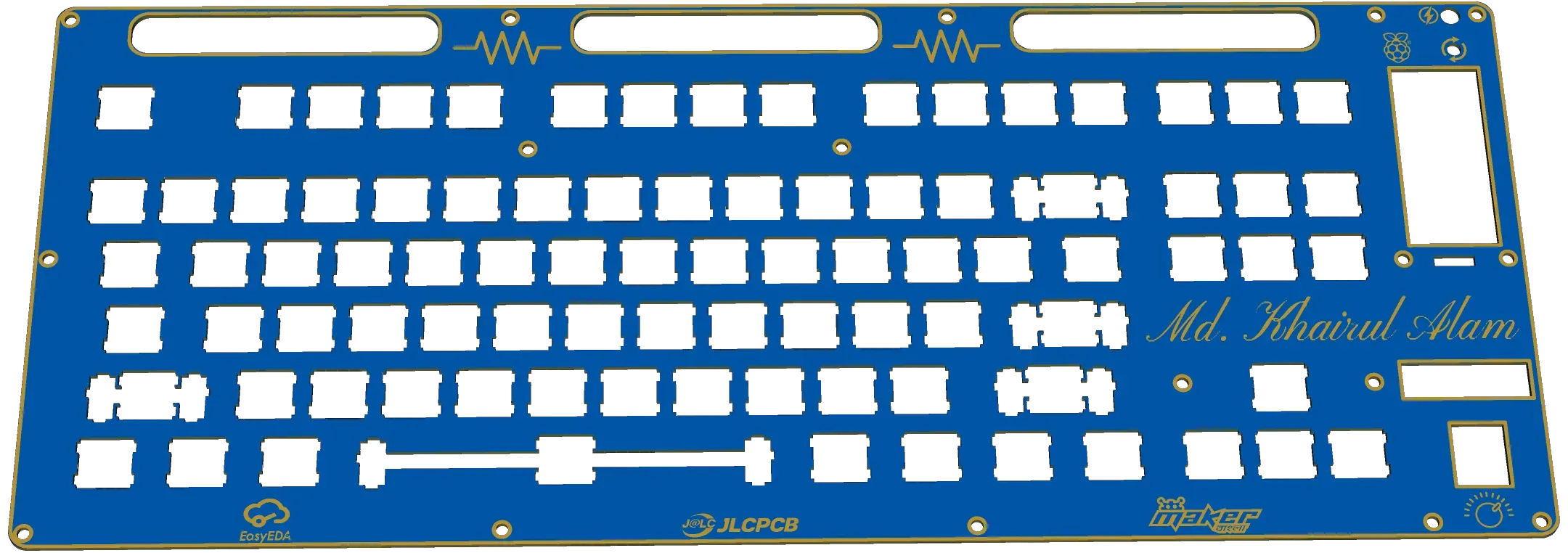
For the plate design, I imported the plate layout DXF and adjusted it to the size of my PCB. To make the three diode sections visible from the top, I placed three dedicated window cutouts positioned directly above the diode sections. Below is the plate layout after finalizing.
3D Layout:
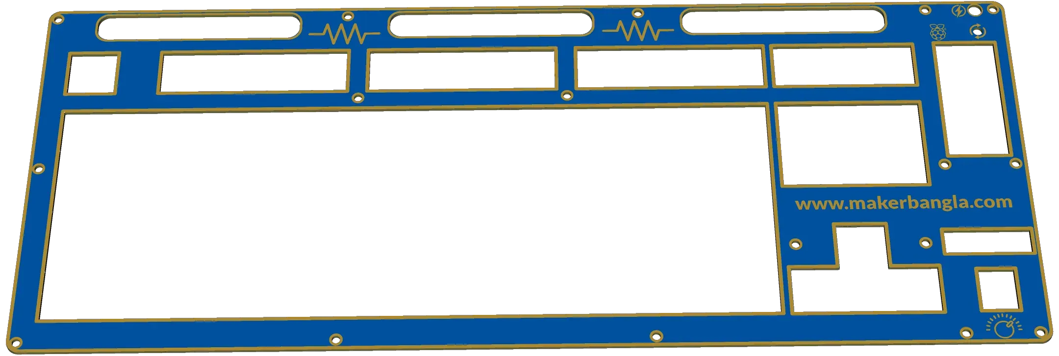
The following is the 3D view of the frame layer of the keyboard.
All three layers of the design were initially integrated within a single EasyEDA project to ensure proper alignment and consistency across the PCB, plate, and frame layers. This approach made it easier to verify component placement, cutouts, and mechanical clearances during the design phase.
Before ordering the PCB, I separated each layer into an individual project and generated the Gerber files.
My project link: 
From the above link, the project can be directly cloned into the EasyEDA editor, where it can be modified as desired.
Ordering the PCB
After completing all design steps and verifying the layout using Design Rule Check (DRC), I ordered the PCB directly from the EasyEDA design tool.
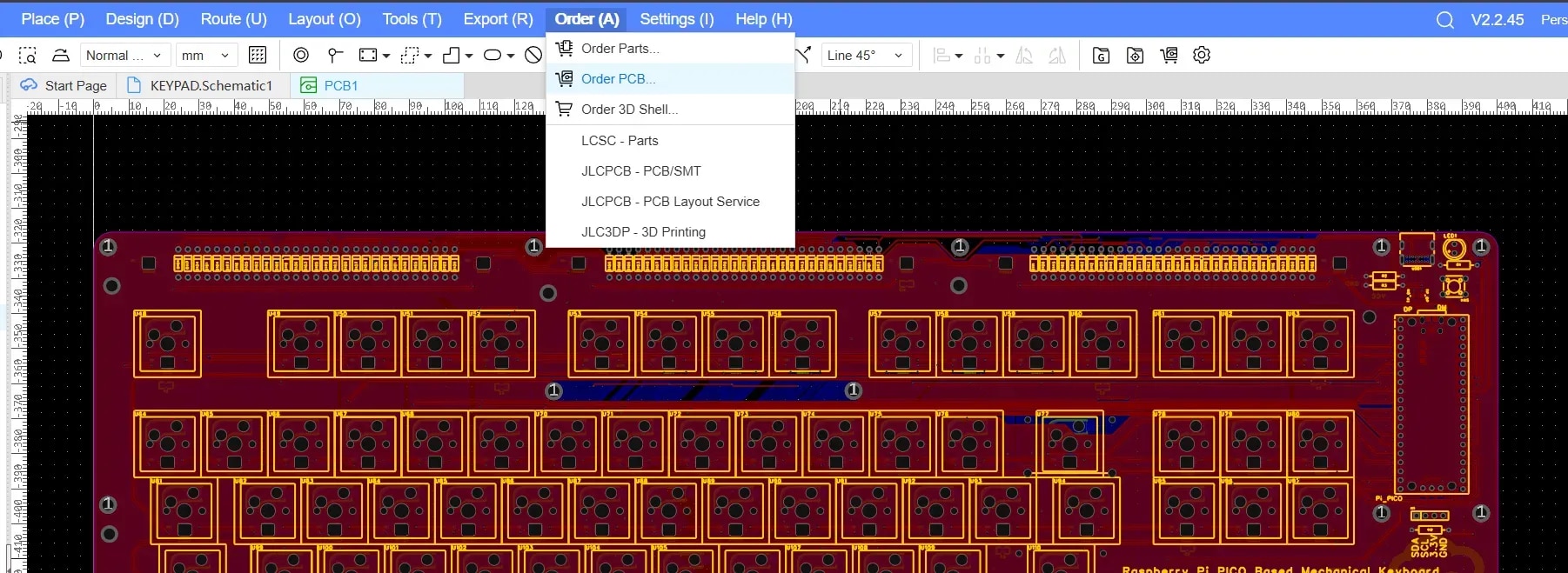
EasyEDA redirects the design directly to JLCPCB, where fabrication parameters such as PCB quantity, board color, thickness, and surface finish can be selected before placing the order.
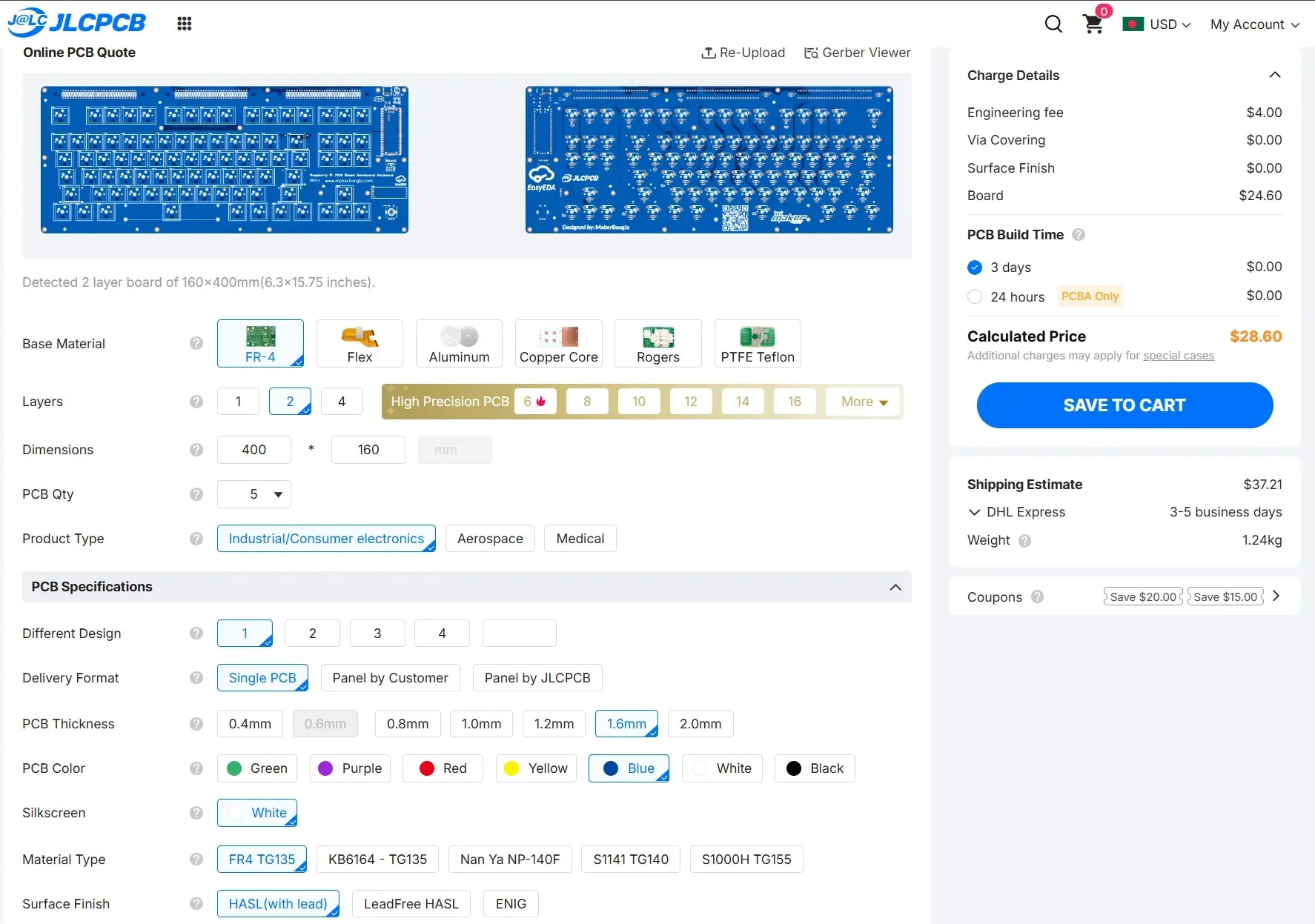
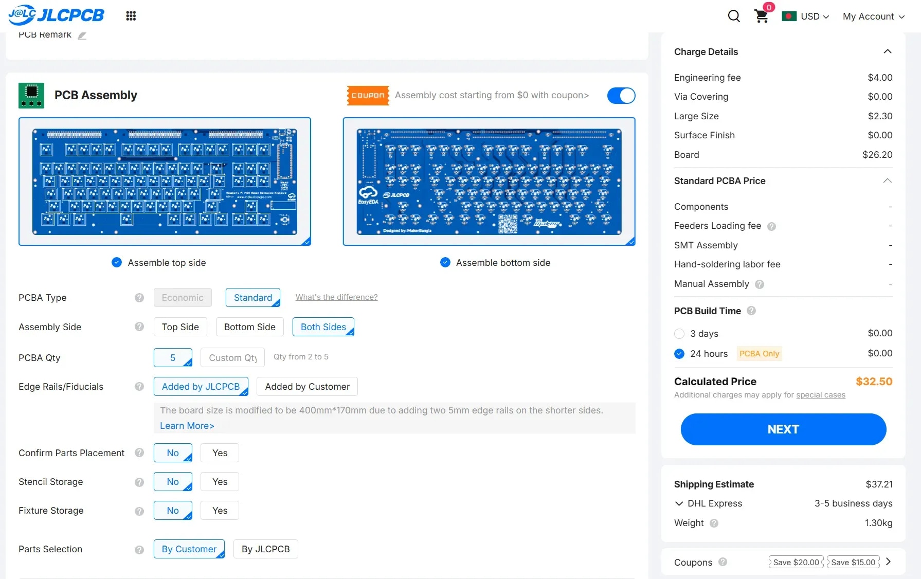
In addition to PCB fabrication, JLCPCB also offers PCB assembly services, which can significantly reduce the effort required to source components from multiple suppliers and manually solder them. I ordered the PCB with the assembly service enabling component assembly on both sides.
Collecting the Components
It usually takes around 25–30 days for the PCBs to arrive. During this waiting period, I collected all the necessary components required to complete the keyboard. The list of components is given below:
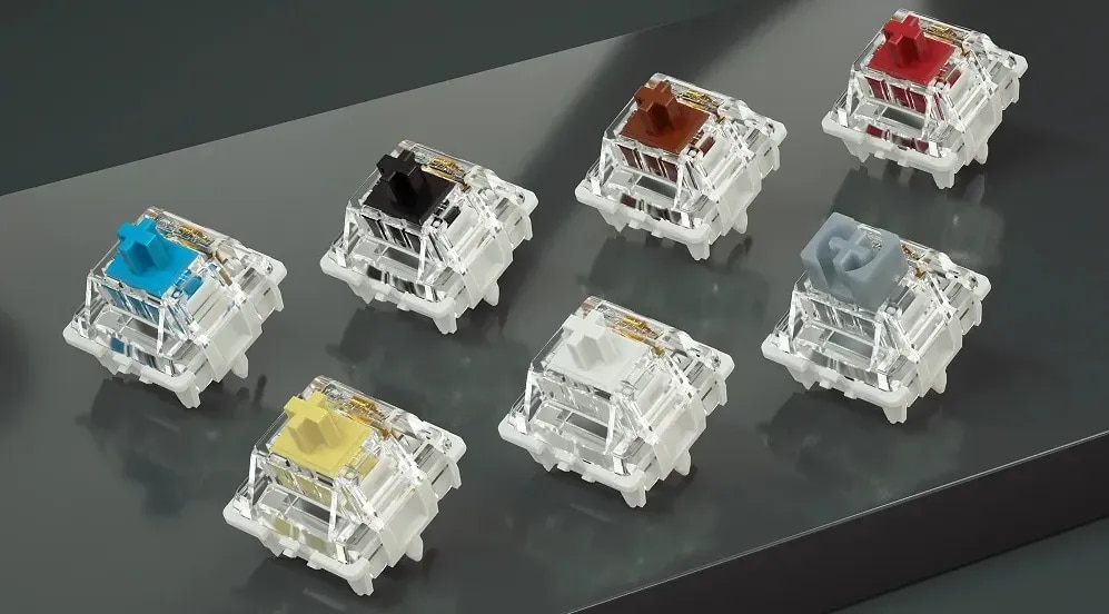
1. GATERON G Pro V3 3.0 Pro Switch (you can choose Clicky or Tacktile, or Linear as your preference)
2. Keycap Set (Totally depends on your choice)
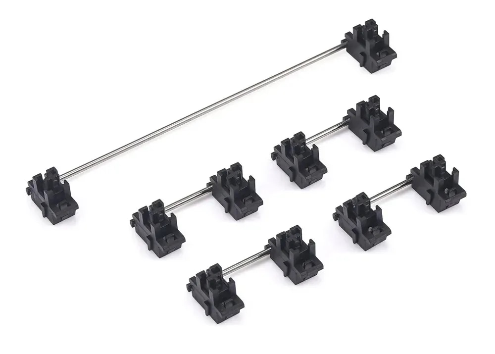
3. Stabilizer for Mechanical Keyboards (you can choose PCB-mounted or plate-mounted; I used plate-mounted)
4. Rubber O Ring Keyboard Switch Dampeners (Optional)
5. 4mm M3 Spacer (hex or round)
6. Aluminum Knobs for Rotary Encoder
7. Official Raspberry Pi Pico Board (with header)
8. M3 Screw and Nut (12mm and 16mm)
| {gallery}Components for Keyboard |
|---|
|
Cherry MX Switch |
|
Keycap Set |
|
Stabilizer plate-mount |
|
Rubber O Ring |
|
Rotary Knob |
|
Raspberry Pi Pico |
|
M3 Nuts and Screws |
|
M3 Spacer 4mm |


Required Tools
1. A generic soldering iron with lead
2. Wire Cutter
3. Screw Driver
25 days later ...
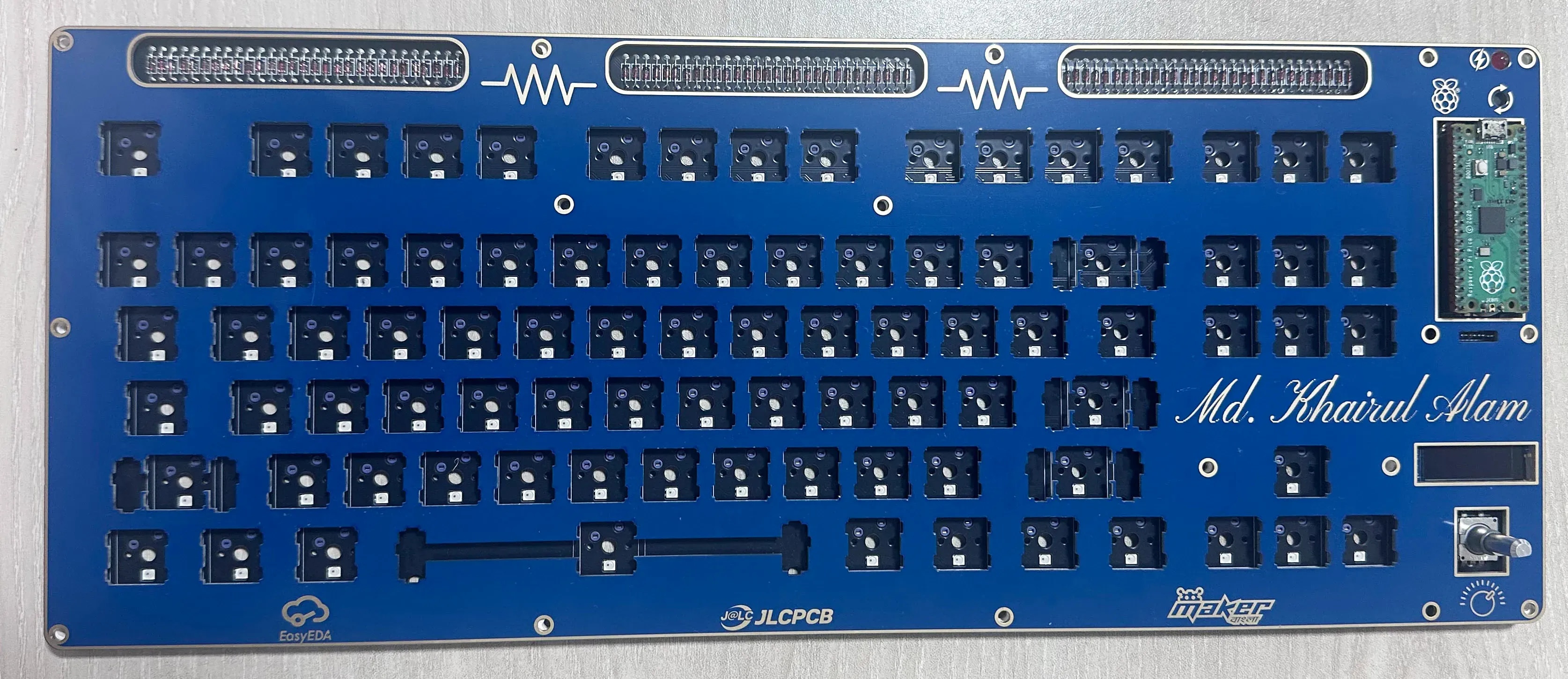
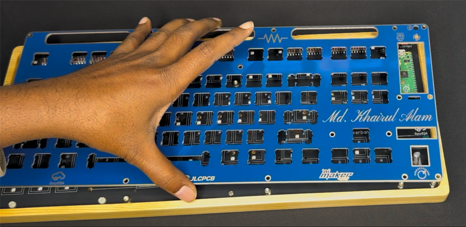
After waiting for around 25 days, I received the PCBs with impressively cool and professional packaging. The following are the top and bottom sides of the base PCB.
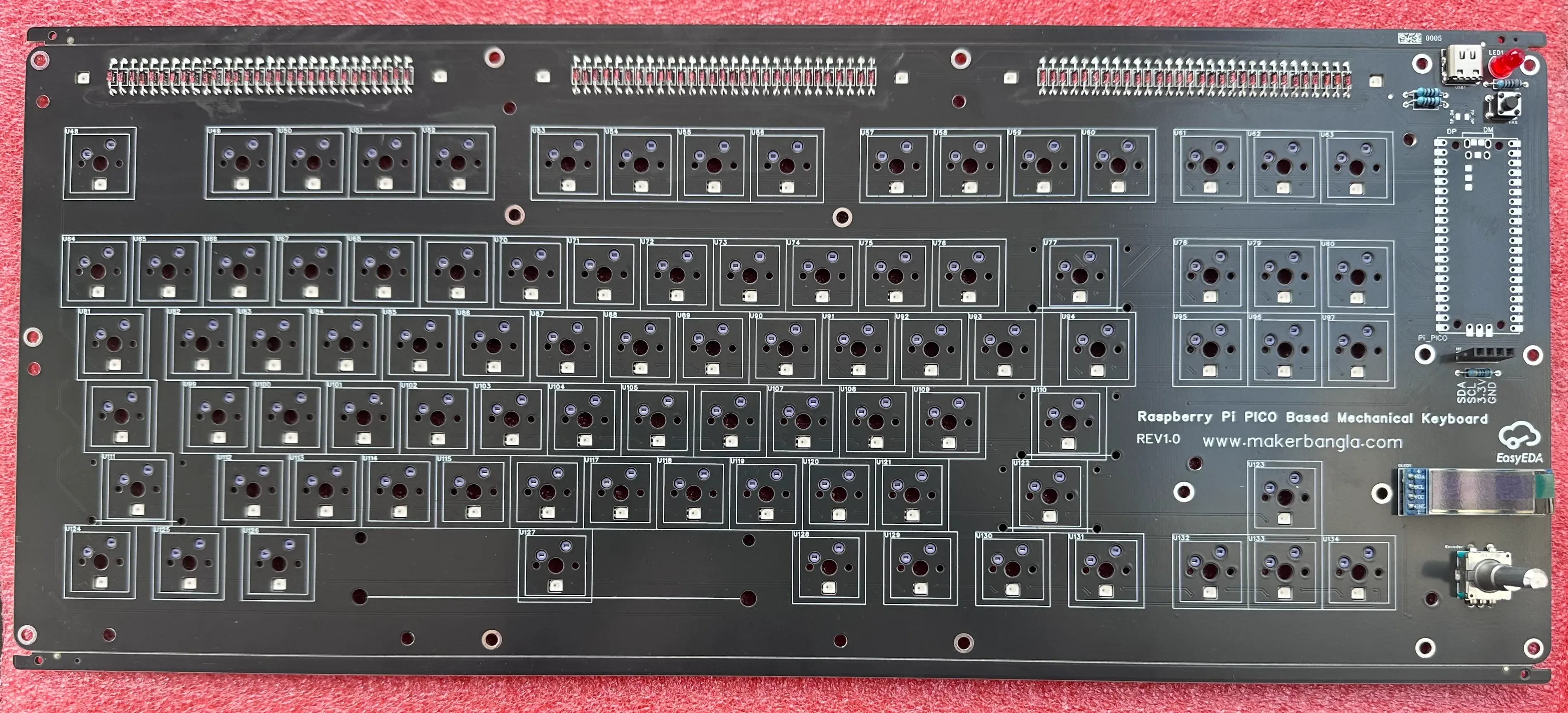
I chose black as the base PCB color for my keyboard because it complements the RGB lighting both functionally and aesthetically. A black PCB absorbs stray light and minimizes unwanted reflections, allowing the RGB LEDs to appear brighter, more vivid, and well-defined under each key.
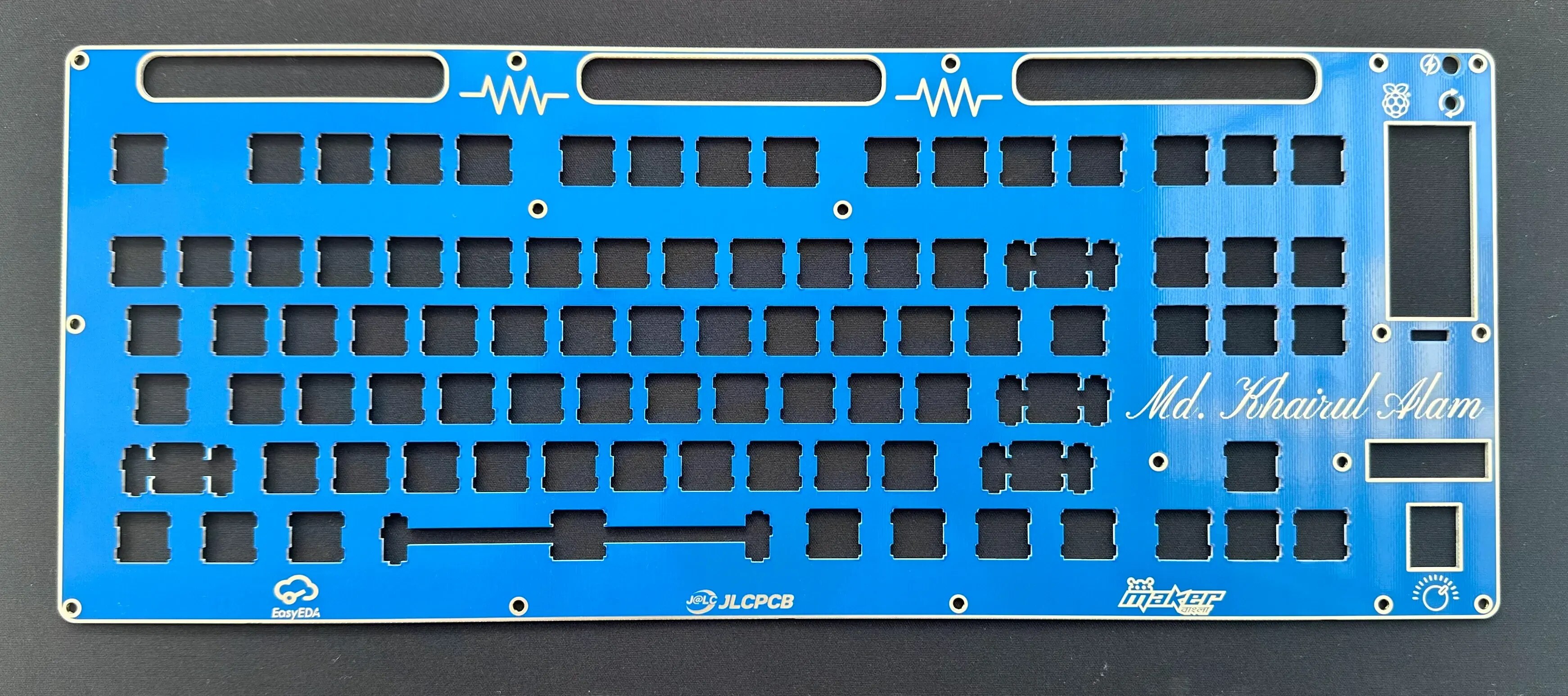
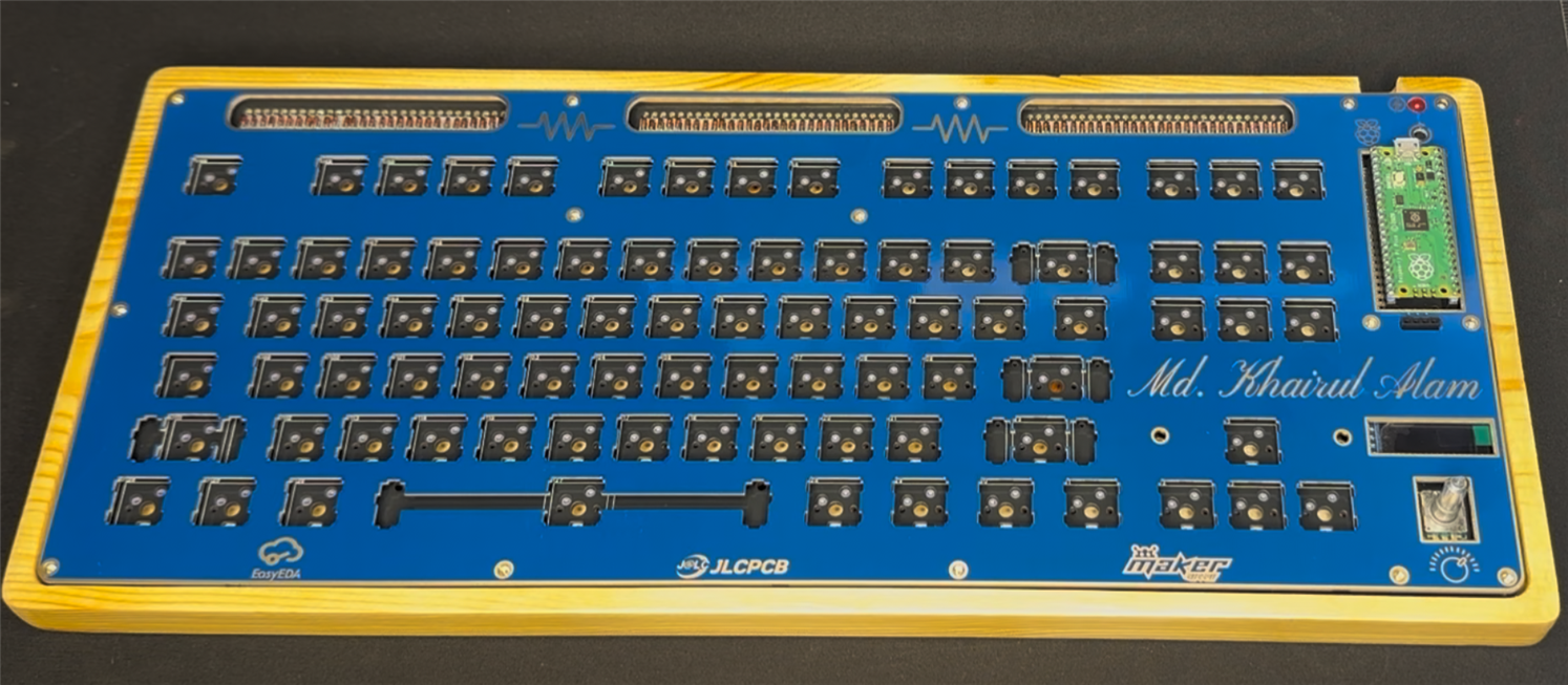
The following is the key switch plate PCB with an attractive blue color. This can be used as a middle layer if you want to use a top case layer, or it can be the top layer:
The following purple gold-plated PCB is the optional top case layer if you like a PCB case for your keyboard.

Assembling the Keyboard
I now have all the necessary components, and the PCBs are in my hand, so it’s time to start assembling the keyboard.

I cut a 5mm thick acrylic sheet to use as a top cover. It is totally optional. You can directly use the top PCB case, or you can even make the switch plate open.
I made two versions of my keyboard. One without using any base. In that case, the bottom PCB will be unsafe. It is better to use a base to protect the PCB and give it a professional look.
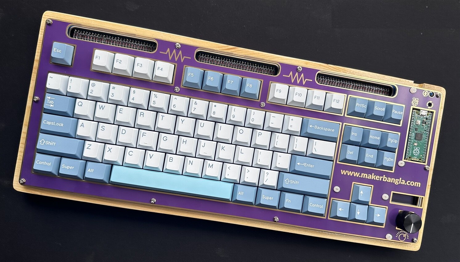
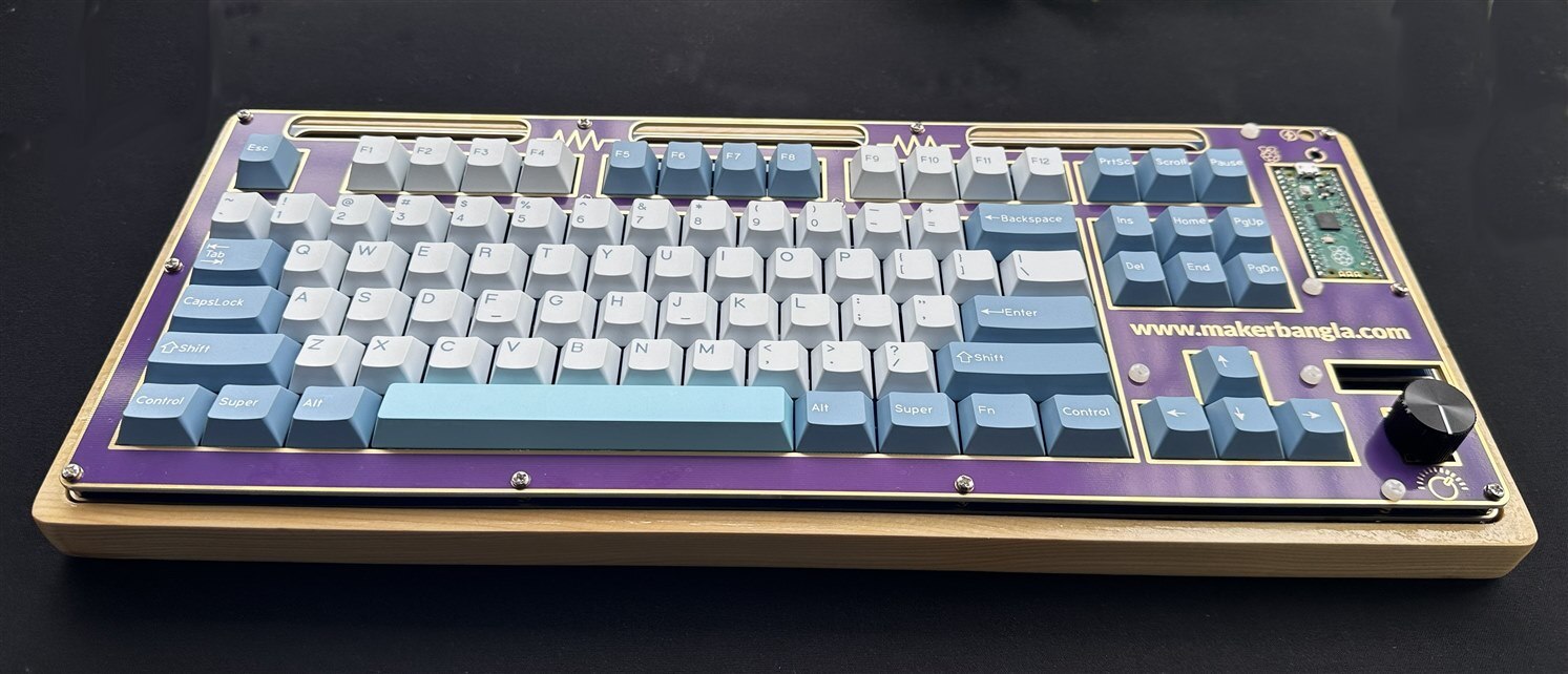
So, in my second version, I used a CNC-cut Pine wood as the base of my keyboard and used the pink PCB as the top case.
My base PCB came with all the components assembled without the Raspberry Pi PICO. So, I manually soldered the Raspberry Pi Pico with two 20-pin female headers.

Then, I placed the plate PCB on top of the base PCB using 4mm long spacers as shown in the image below.
Then I installed the plate-mount stabilizers in the plate.
I placed the acrylic frame on top of the plate and fixed all the layers together using 15mm M3 screws and nuts.

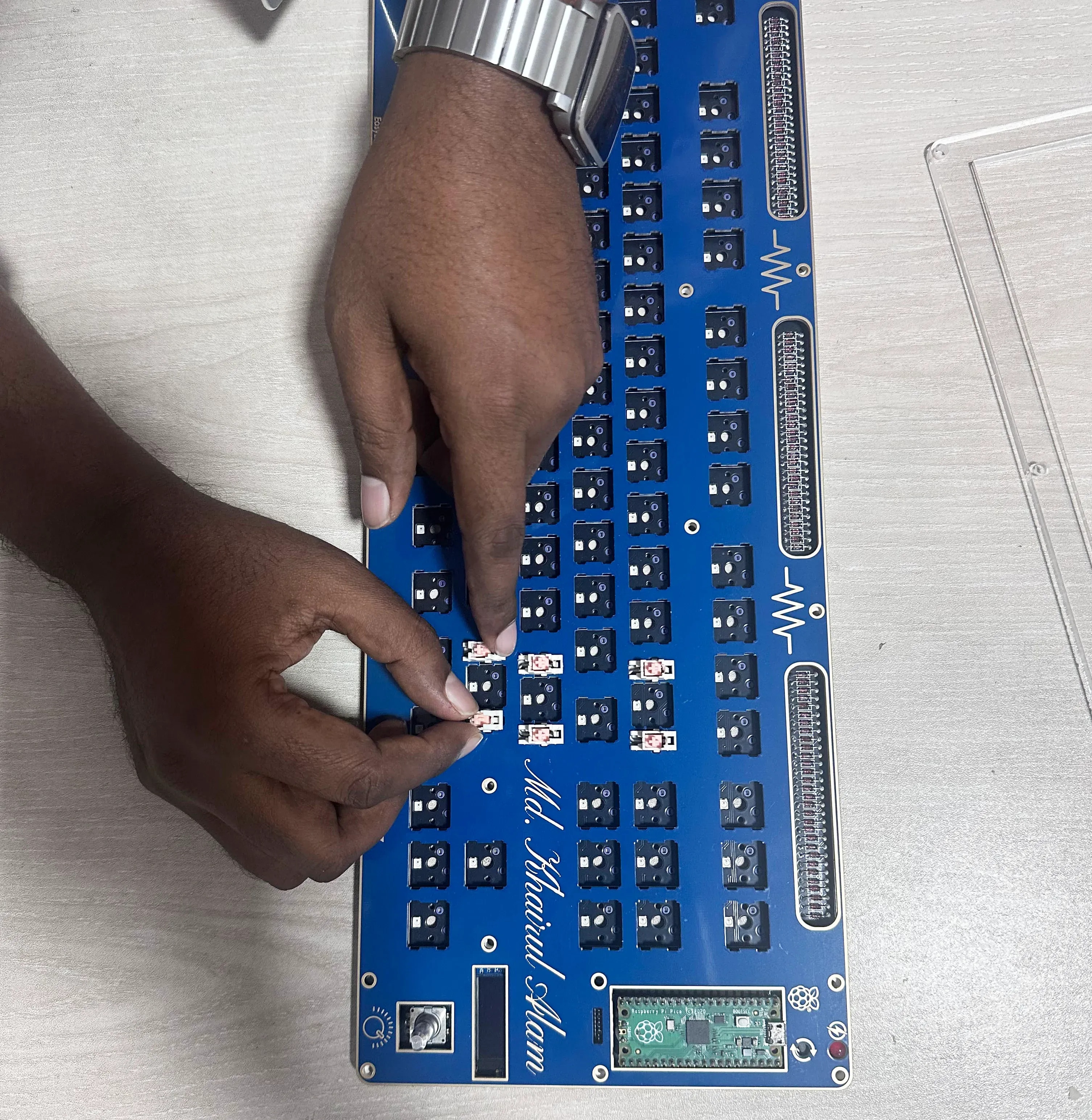
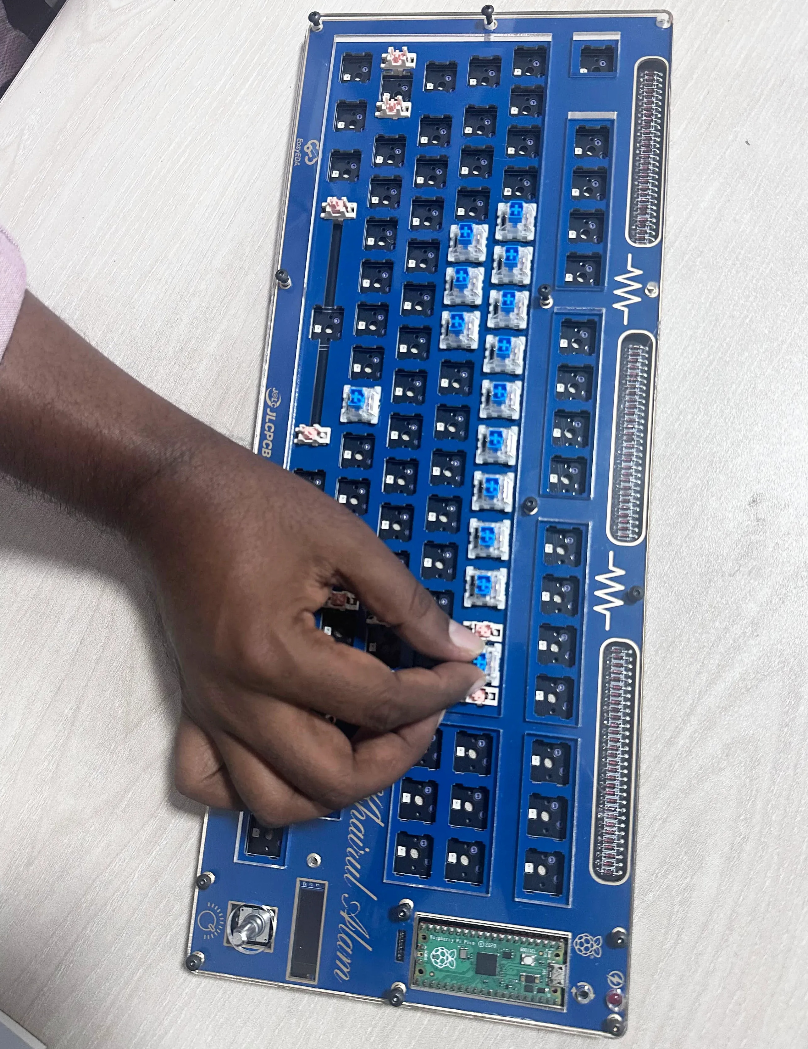
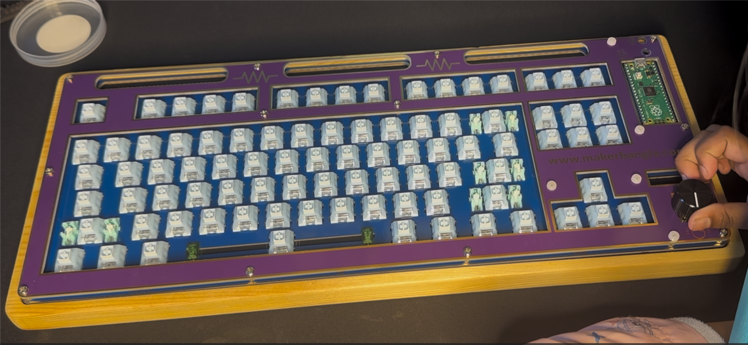
Then I installed the switches.
Developing the Firmware
After placing the switches, the next step is to upload the firmware to the Raspberry Pi PICO. I developed the firmware using the QMK (Quantum Mechanical Keyboard) firmware library. QMK is an open-source and widely used platform for custom mechanical keyboards. QMK provides a flexible framework to define keymaps, layers, and advanced features such as macros, RGB lighting control, rotary encoders, and custom behaviors.
For developing the QMK firmware, you need to set up the environment. I set up my Windows PC following the official guidelines from the link: https://docs.qmk.fm/newbs. Environment setup is only necessary if you want to modify the code and recompile it. If you have any precompiled firmware (***.uf2) you can directly drag it to your Raspberry Pi PICO, and you are done. I have attached my precompiled firmware to my GitHub.
Full code with precompiled firmware and schematic is available on my GitHub: https://github.com/taifur20/pico_tkl
Version 1 Finished
In version one, there is no protective base on the bottom, and a transparent laser-cut acrylic sheet is used on top of the plate.

Version 2 (using wooden base)
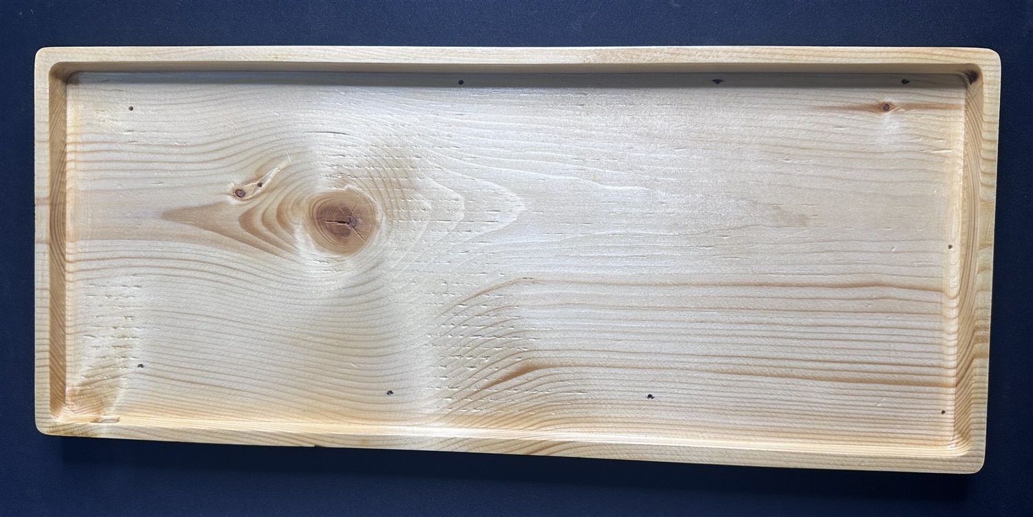
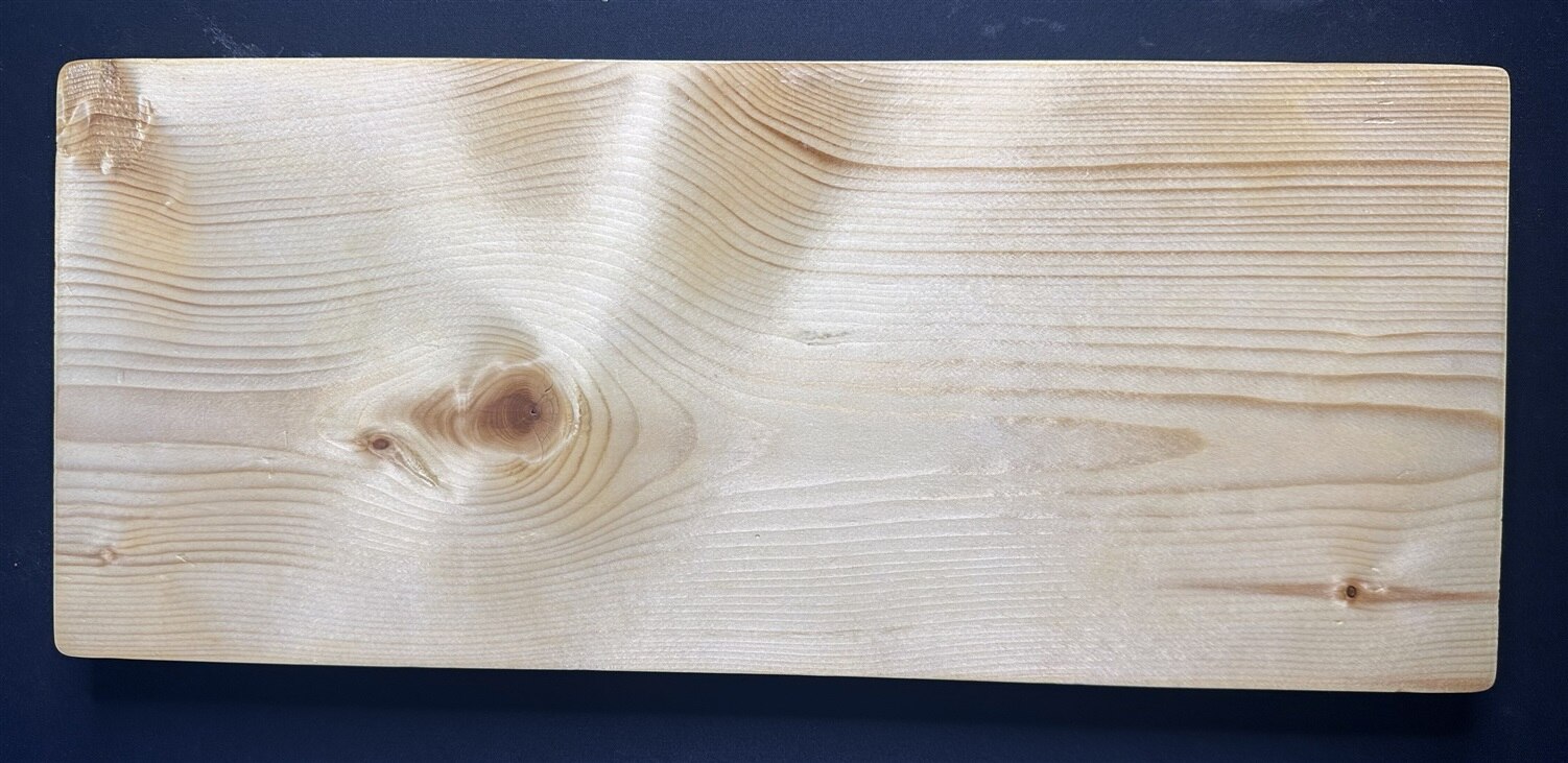
For version 2 of my keyboard, I selected pine wood base. According to the measurement of my PCB I cut and engraved the pine wood using CNC machine. I sanded the piece and applied wood preservative to protect it from the environment.
The following are the top and bottom view of the final pine base.
To mount the PCB onto the base, I drilled several holes using a 2 mm drill bit to insert the M3 hex spacers. Then I installed M3 3 mm × 3 mm female–male hex spacers into the holes and secured them using a hex driver.
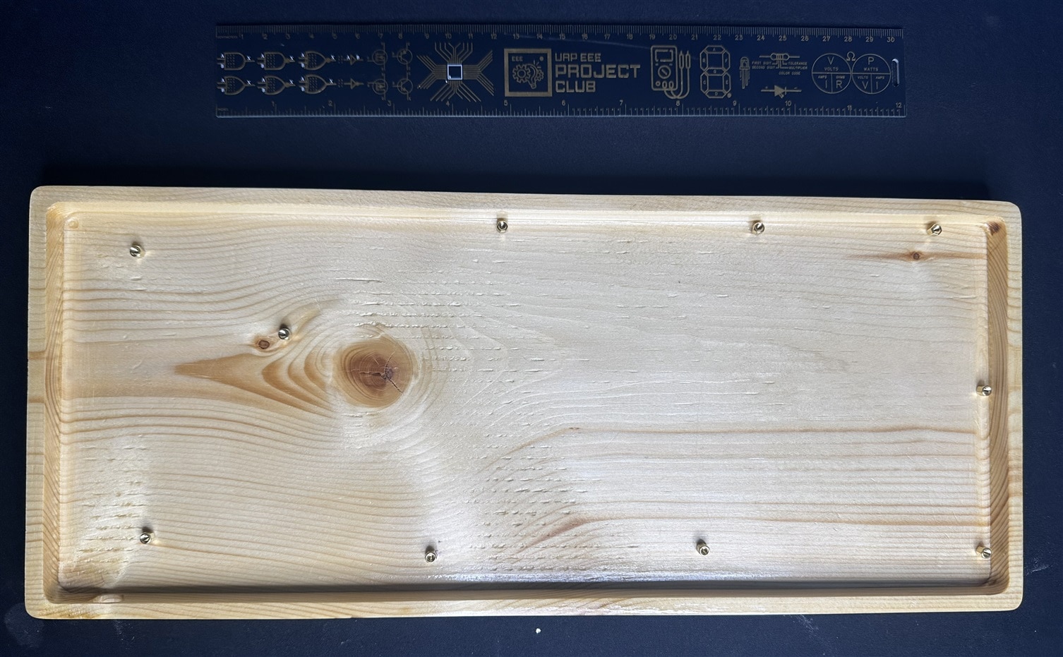
Then I inserted the M3 4 mm × 4 mm female–male hex spacers into the base PCB and fixed them with M3 nuts.


I placed the base PCB onto the wooden base and secured it using M3, 4mm screws.

I inserted the Raspberry Pi Pico into the previously soldered female header.

After fixing the base PCB on the pine base and inserting the Raspberry Pi Pico, I attached the plate and the top case.
Then I placed the stabilizers, switches, and the keycaps as like as version 1.

Before adding the keycap, I checked the keyboard using https://en.key-test.ru/ to confirm that every key is working.
I encountered an issue with a few of the switches where they were not seating properly. To resolve this, I carefully reopened the assembly and inspected the switches. I discovered that some of the pins had bent during insertion, preventing proper alignment with the hot-swap sockets. I straightened the pins, reinstalled the affected switches, and ensured each one was firmly and correctly positioned.

After confirming that all switches functioned perfectly and the keyboard worked as expected, I installed the keycaps.

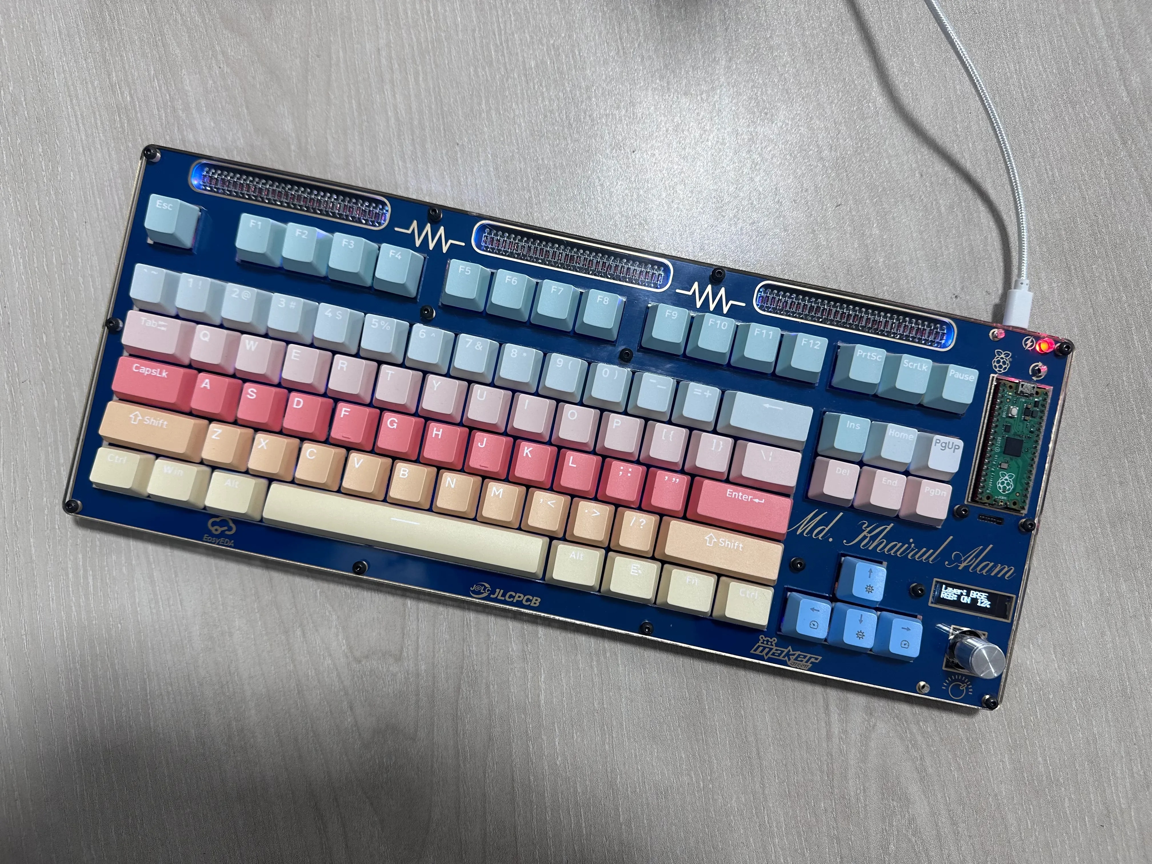
The final keyboard looks like this.
You can watch the following assembly video:
Holiday Effect
To bring a festive and celebratory mode to my keyboard, I created a custom RGB matrix user file and added a few holiday effects related to Christmas, Winter, and New Year. I also added holiday-specific greetings on the OLED display.
This is the code for generating holiday-specific custom effects:
// !!! DO NOT ADD #pragma once !!! //
#define LED_COUNT 87
// Step 1.
// Declare custom effects using the RGB_MATRIX_EFFECT macro
// (note the lack of semicolon after the macro!)
RGB_MATRIX_EFFECT(CHRISTMAS_WAVE)
RGB_MATRIX_EFFECT(CHRISTMAS_CANDY_CANE)
RGB_MATRIX_EFFECT(WINTER_SNOW)
RGB_MATRIX_EFFECT(WINTER_BLIZZARD)
RGB_MATRIX_EFFECT(NEWYEAR_FIREWORKS)
RGB_MATRIX_EFFECT(NEWYEAR_FIREWORKS_GLOW)

// Step 2.
// Define effects inside the `RGB_MATRIX_CUSTOM_EFFECT_IMPLS` ifdef block
#ifdef RGB_MATRIX_CUSTOM_EFFECT_IMPLS

static bool CHRISTMAS_WAVE(effect_params_t *params) {
    RGB_MATRIX_USE_LIMITS(led_min, led_max);

    uint8_t step = (params->iter / 8) & 1;

    for (uint8_t i = led_min; i < led_max && i < LED_COUNT; i++) {
        if (((i + step) & 1) == 0) {
            rgb_matrix_set_color(i, 255, 0, 0);   // Red
        } else {
            rgb_matrix_set_color(i, 0, 255, 0);   // Green
        }
    }
    return rgb_matrix_check_finished_leds(led_max);
}

static bool CHRISTMAS_CANDY_CANE(effect_params_t *params) {
    RGB_MATRIX_USE_LIMITS(led_min, led_max);

    uint8_t phase = (params->iter / 6) % 4;

    for (uint8_t i = 0; i < LED_COUNT; i++) {
        uint8_t p = (i + phase) % 4;

        if (p < 2) {
            rgb_matrix_set_color(i, 255, 0, 0);     // Red
        } else {
            rgb_matrix_set_color(i, 255, 255, 255); // White
        }
    }
    return rgb_matrix_check_finished_leds(led_max);
}


static bool WINTER_SNOW(effect_params_t *params) {
    RGB_MATRIX_USE_LIMITS(led_min, led_max);

    for (uint8_t i = led_min; i < led_max && i < LED_COUNT; i++) {
        if ((rand() & 0x1F) == 0) {
            rgb_matrix_set_color(i, 255, 255, 255); // Snowflake
        } else {
            rgb_matrix_set_color(i, 0, 0, 40);      // Cold blue
        }
    }
    return rgb_matrix_check_finished_leds(led_max);
}

static bool WINTER_BLIZZARD(effect_params_t *params) {
    RGB_MATRIX_USE_LIMITS(led_min, led_max);

    uint8_t offset1 = (params->iter / 4) % LED_COUNT;
    uint8_t offset2 = (params->iter / 7) % LED_COUNT;

    for (uint8_t i = 0; i < LED_COUNT; i++) {
        rgb_matrix_set_color(i, 0, 0, 10); // dark blue background
    }

    rgb_matrix_set_color(offset1, 180, 180, 255);
    rgb_matrix_set_color(offset2, 120, 120, 255);
    return rgb_matrix_check_finished_leds(led_max);
}

static bool NEWYEAR_FIREWORKS(effect_params_t *params) {
    RGB_MATRIX_USE_LIMITS(led_min, led_max);

    for (uint8_t i = led_min; i < led_max && i < LED_COUNT; i++) {
        if ((rand() & 0x0F) == 0) {
            rgb_matrix_set_color(
                i,
                rand() & 0xFF,
                rand() & 0xFF,
                rand() & 0xFF
            );
        } else {
            rgb_matrix_set_color(i, 0, 0, 0);
        }
    }
    return rgb_matrix_check_finished_leds(led_max);
}

static uint8_t firework_step = 0;
static uint8_t firework_x = 0;
static uint8_t firework_y = 0;

static bool NEWYEAR_FIREWORKS_GLOW(effect_params_t *params) {
    RGB_MATRIX_USE_LIMITS(led_min, led_max);

    // Start a new firework
    if (firework_step == 0) {
        uint8_t center = rand() % LED_COUNT;
        firework_x = g_led_config.point[center].x;
        firework_y = g_led_config.point[center].y;
        firework_step = 1;
    }

    for (uint8_t i = led_min; i < led_max && i < LED_COUNT; i++) {
        int16_t dx = g_led_config.point[i].x - firework_x;
        int16_t dy = g_led_config.point[i].y - firework_y;

        // Approximate circular distance (fast, no sqrt)
        uint16_t dist = abs(dx) + abs(dy);

        int16_t brightness = 255 - (dist * 20) - (firework_step * 18);

        if (brightness > 0) {
            rgb_matrix_set_color(
                i,
                brightness,
                brightness / 2,
                255
            );
        } else {
            rgb_matrix_set_color(i, 0, 0, 0);
        }
    }

    firework_step++;

    // Reset after full burst
    if (firework_step > 12) {
        firework_step = 0;
    }

    return rgb_matrix_check_finished_leds(led_max);
}


#endif // RGB_MATRIX_CUSTOM_EFFECT_IMPLS
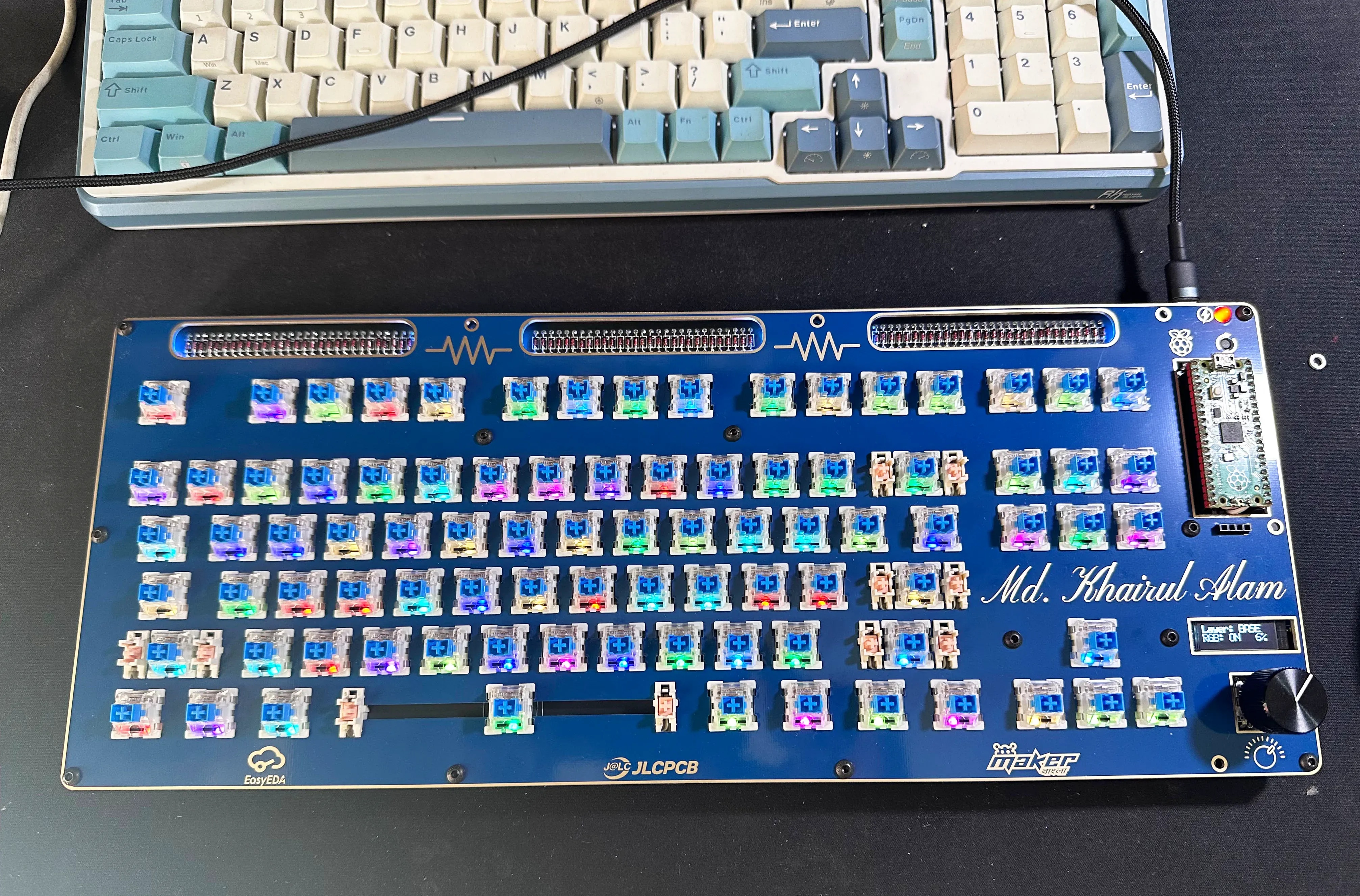
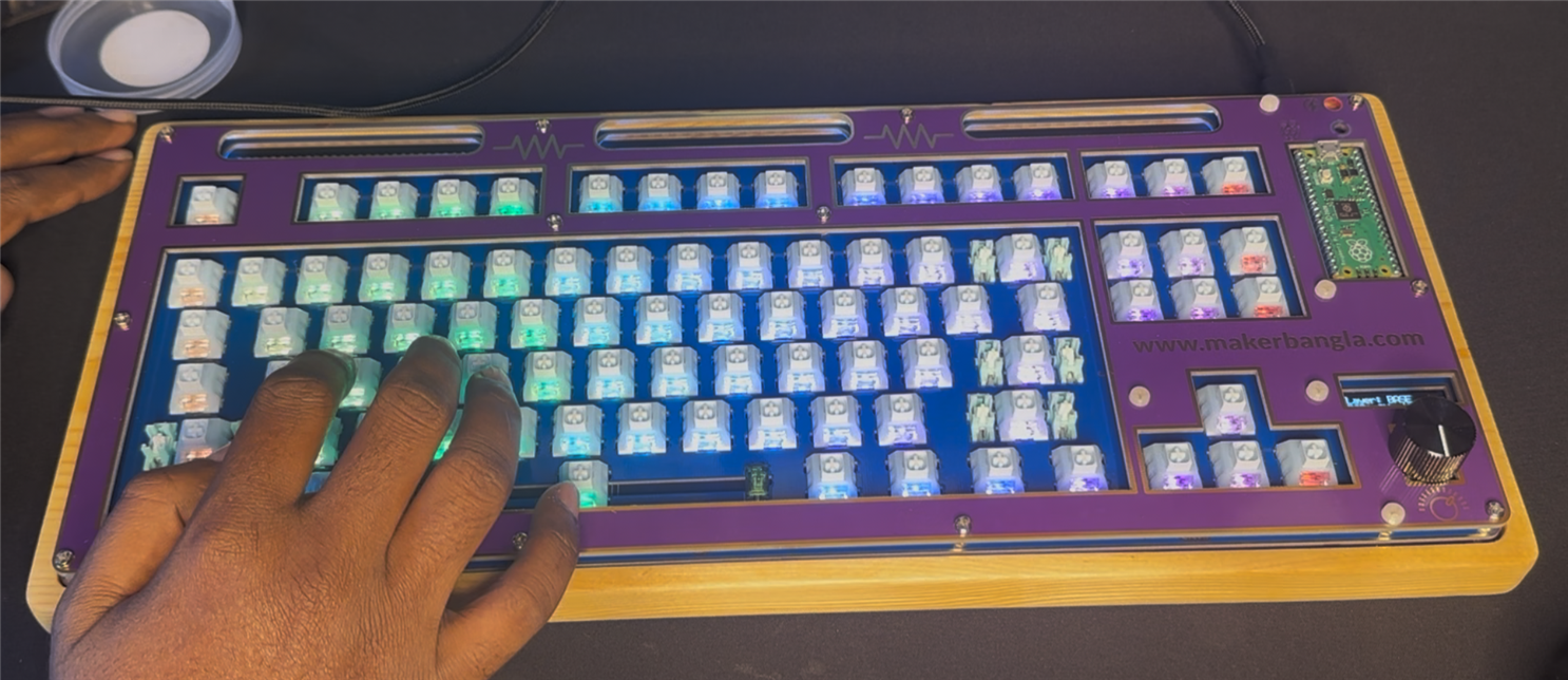
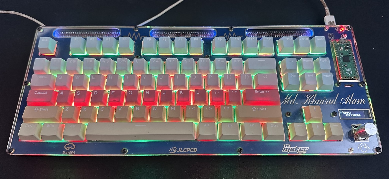
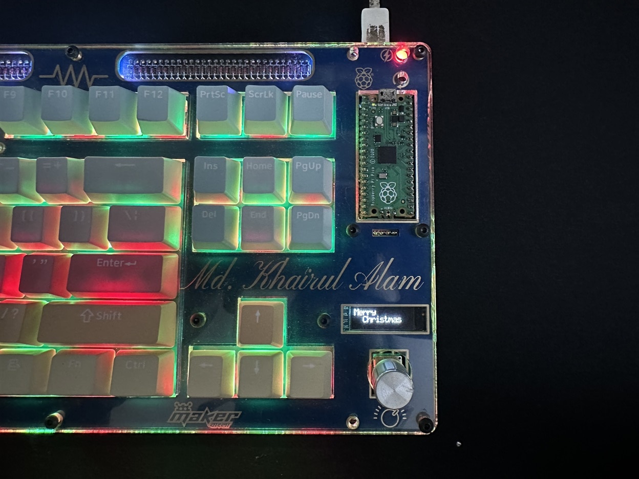
After enabling the Christmas wave effect, the keyboard looks very gorgeous. See the following image, though practically it looks more attractive than the photo:
I designed this holiday-themed keyboard to go beyond the traditional nature of an input device and transform it into an interactive, expressive platform that reflects seasonal joy and cultural celebrations. By integrating custom RGB matrix animations and contextual OLED messages for events such as Christmas, Winter season, and the New Year, the keyboard becomes a dynamic medium for storytelling and atmosphere. It allows users to visually celebrate holidays at their workspace, during live streams, exhibitions, or community events, making technology feel more personal and emotionally engaging.
I implemented 2 layers in my keyboard. Layer 1 is for general use, and Layer 2 is for some advanced options, like changing the RGB effect, adjusting brightness, increasing the audio level, etc. To enable or change the holiday effect, you have to go to layer 2 by using the rotary encoder and pressing the buttons from 1 to 8 to change the holiday effect. Different button has different effects. When a holiday effect is active, the related greeting is automatically displayed on the OLED display.
This keyboard can be a wonderful holiday gift for your friend and someone special, combining daily usability with a personal and festive touch.
Attachments
References
1. https://www.keyboard-layout-editor.com/
2. http://builder.swillkb.com/