element14 Community
element14 Community
    Register Log In
  • Site
  • Search
  • Log In Register
  • Community Hub
    Community Hub
    • What's New on element14
    • Feedback and Support
    • Benefits of Membership
    • Personal Blogs
    • Members Area
    • Achievement Levels
  • Learn
    Learn
    • Ask an Expert
    • eBooks
    • element14 presents
    • Learning Center
    • Tech Spotlight
    • STEM Academy
    • Webinars, Training and Events
    • Learning Groups
  • Technologies
    Technologies
    • 3D Printing
    • FPGA
    • Industrial Automation
    • Internet of Things
    • Power & Energy
    • Sensors
    • Technology Groups
  • Challenges & Projects
    Challenges & Projects
    • Design Challenges
    • element14 presents Projects
    • Project14
    • Arduino Projects
    • Raspberry Pi Projects
    • Project Groups
  • Products
    Products
    • Arduino
    • Avnet & Tria Boards Community
    • Dev Tools
    • Manufacturers
    • Multicomp Pro
    • Product Groups
    • Raspberry Pi
    • RoadTests & Reviews
  • About Us
  • Store
    Store
    • Visit Your Store
    • Choose another store...
      • Europe
      •  Austria (German)
      •  Belgium (Dutch, French)
      •  Bulgaria (Bulgarian)
      •  Czech Republic (Czech)
      •  Denmark (Danish)
      •  Estonia (Estonian)
      •  Finland (Finnish)
      •  France (French)
      •  Germany (German)
      •  Hungary (Hungarian)
      •  Ireland
      •  Israel
      •  Italy (Italian)
      •  Latvia (Latvian)
      •  
      •  Lithuania (Lithuanian)
      •  Netherlands (Dutch)
      •  Norway (Norwegian)
      •  Poland (Polish)
      •  Portugal (Portuguese)
      •  Romania (Romanian)
      •  Russia (Russian)
      •  Slovakia (Slovak)
      •  Slovenia (Slovenian)
      •  Spain (Spanish)
      •  Sweden (Swedish)
      •  Switzerland(German, French)
      •  Turkey (Turkish)
      •  United Kingdom
      • Asia Pacific
      •  Australia
      •  China
      •  Hong Kong
      •  India
      • Japan
      •  Korea (Korean)
      •  Malaysia
      •  New Zealand
      •  Philippines
      •  Singapore
      •  Taiwan
      •  Thailand (Thai)
      • Vietnam
      • Americas
      •  Brazil (Portuguese)
      •  Canada
      •  Mexico (Spanish)
      •  United States
      Can't find the country/region you're looking for? Visit our export site or find a local distributor.
  • Translate
  • Profile
  • Settings
Personal Blogs
  • Community Hub
  • More
Personal Blogs
Legacy Personal Blogs 5 - Input Connections & PiFace Digital Emulator
  • Blog
  • Documents
  • Mentions
  • Sub-Groups
  • Tags
  • More
  • Cancel
  • New
  • Share
  • More
  • Cancel
Group Actions
  • Group RSS
  • More
  • Cancel
Engagement
  • Author Author: ge0rgej
  • Date Created: 5 Sep 2013 8:50 PM Date Created
  • Views 550 views
  • Likes 0 likes
  • Comments 0 comments
  • piface_emulator
  • piface_digital
  • raspberry_pi
Related
Recommended

5 - Input Connections & PiFace Digital Emulator

ge0rgej
ge0rgej
5 Sep 2013

image


In the last section we saw where the components used in this project wil be connected - now lets start putting this into practice.


You may recall that in Section 2, ( Required Components ), I mentioned about using a 4 gang light switch to simulate the float switches being operated ...... far much better than running into the Garden and getting your hands wet.


Below you can see how the light switch and the PiFace Digital inputs should be connected.


image


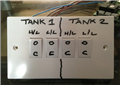
As you can see I have used a common household four gang light switch to simulate the high level and low level float switches in Tank 1 and Tank 2.

As we look at the picture, opposite, all four switches are currently in the ( C ) closed switch state which will indicate that all four float switches have been activated, the water tanks are full and the mains water solenoid valve is closed.


image

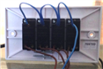
Now lets look at the connections on the back of the switch. All four common terminals on the switches are looped together (the blue cable) - with a link from the last common terminal back to the PiFace input terminal ( 0v )


You will also note that four brown cables are connected to the L1 terminals on the switches - these need to be connected as shown below;


Tank 1 H/L connect to PiFace Input Pin 0 | Tank1 L/L connect to PiFace Input Pin 1

Tank 2 H/L connect to PiFace Input Pin 2 | Tank 2 L/L connect to PiFace Input Pin 3


image


When all connections have been made you should have something resembling this.


You have probably noticed that we have not yet connected anything to the output changeover relays. Rather than getting overloaded with information at this early stage we will be dealing with outputs a bit later. The first Python code that we run will deal specifically with monitoring the float switches and reporting their switch state.


When it comes to connecting up our float switches at the end of this project you will notice that there is virtually no difference to what we have just carried out above.


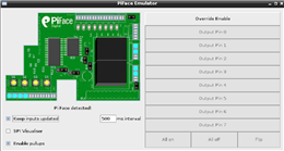
If you have previously installed PiFace Digital as described in Section 3b and have made all the connections detailed above you are now ready to see some action in the PiFace Emulator


In the Linux Terminal at the command prompt;


type : $ piface/scripts/piface-emulator


If all is well the PiFace Emulator should execute as shown in the video below.


On the left hand side of the emulator enable the check box labelled 'Keep Inputs Updated', Providing that all of the switches are in the closed position you should see the four inputs highlighted as shown.  Now toggle the switches on and off and the emulator will update the switch state.


If you keep your eye on the output changeover relays whilst toggling the input switches on and off you will notice that nothing is happening with the relays. This is to be expected as we have not yet initiated our Python code to instruct the relays to switch over.image


Now head over to the right hand side of the emulator and click on 'Override Enable'. You will recall in the last section that I mentioned we would be using code to activate Output Pin 0 and Output Pin 1 - click on each of these and you will see how the relays switch over from the (n/c) terminal to the (n/o) terminal.


You don't have permission to edit metadata of this video.
Edit media
x
image
Upload Preview
image


In the next section we will explore Python ( IDLE and Interactive Mode ) and run the code for monitoring our float switches

  • Sign in to reply
element14 Community

element14 is the first online community specifically for engineers. Connect with your peers and get expert answers to your questions.

  • Members
  • Learn
  • Technologies
  • Challenges & Projects
  • Products
  • Store
  • About Us
  • Feedback & Support
  • FAQs
  • Terms of Use
  • Privacy Policy
  • Legal and Copyright Notices
  • Sitemap
  • Cookies

An Avnet Company © 2025 Premier Farnell Limited. All Rights Reserved.

Premier Farnell Ltd, registered in England and Wales (no 00876412), registered office: Farnell House, Forge Lane, Leeds LS12 2NE.

ICP 备案号 10220084.

Follow element14

  • X
  • Facebook
  • linkedin
  • YouTube