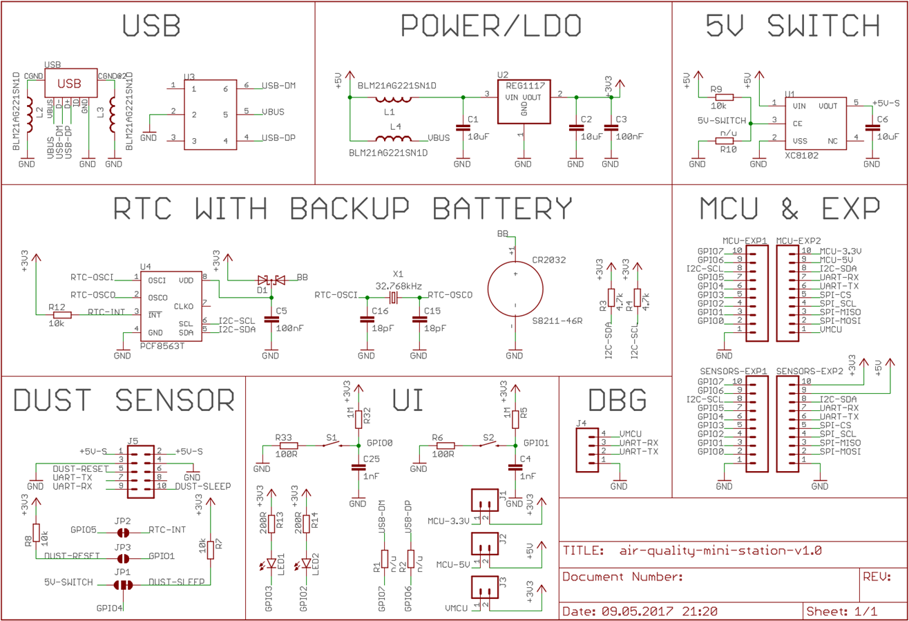
A long weekend is gone and it is time for an update. I have created a schematic for the Air Quality Mini Station project. For the main subsystems I have used:
- USB - micro USB connector with ESD protection chip
- POWER/LDO - filtering ferrite beads and LM1117 (3.3V), since I have many of them laying around (in the next revision I might use something with lower quiescent current to prolong battery life)
- 5V SWITCH - a dust sensor I want to use (PMS7003) has a sleep mode, but if someone wants to use sensor which does not have this capability, I implemented on/off power switch (XC8102) in order to save energy between measurements
- RTC - I used one of the simplest real time clock from NXP (PCF8563T) to pair measurements data with timestamps; I also added CR2032 battery as a backup for the RTC
- DUST SENSOR - it is PMS7003 model
- UI - there are two buttons and two LEDs
- DBG - this connector is for reading raw data from the dust sensor
- MCU & EXP - I used only headers for this board; I think I will start with adding Thunder Board Sense from Silicon Labs as a start (MCU + BLE) and then maybe I could do a small WiFi shield instead to connect to this PCB; EXP headers are mainly for other sensors (temperature, humidity, pressure, etc.) that I may or may not use in the first iteration
Let me know in the comments what do you think of this modular approach in the schematic for the Air Quality Mini Station project. Now, it is routing time.